TAA-101/TAA-101S Antenna Actuator Manual | Doc. No. 605169301 Rev. M
Broadcast Microwave Services, Inc.
22
6. Install actuator.
3.1
Deciding the Component Locations
The placement of the mounting bracket and actuator are a function of aircraft structure, center of gravity,
pilot visibility and functionality. The attachment of the mounting bracket must be structurally sound. The
location should be such that the pilot can easily see whether the antenna is deployed or not. The actuator
is mounted inboard so that antenna is deployed against forward motion. The “Forward” signage on the
actuator must always face toward the front of the aircraft.
NOTE: The TAA-101/TAA-101S must be installed on the side specified at the time of order.
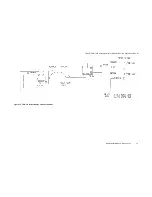
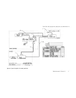
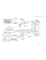
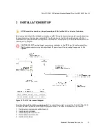
The cables are routed through the helicopter from the aircraft power to the Up/Down box, then from the
Up/Down Box to the TAA-101 or TAA-101S. The RF cable from the transmitter will be routed to the
Mounting Bracket of the TAA-101 and TAA-101S. The smaller RF cable routes from the Mounting Bracket
to the Omni Antenna.
The Deployment Control Unit is installed in the cockpit within reach of the pilot. There are several types of
Deployment Control for the TAA-101 and TAA-101S. The Up/Down Box is the only unit with the sole
function to deploy and retract the antenna actuator. Other Deployment Control Units have additional
features and are not covered by this documentation. Please refer to the proper documentation on the
specific Deployment Control Unit for information on installation, operation and maintenance.
3.2
Installing the Mounting Bracket
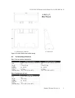
The TAA-101 or TAA-101S is attached to the helicopter by a Mounting Bracket. The specific mounting
bracket was selected at the time of order. Installation procedures for each type are as follows:
•
Skid Mount Bracket Installation
•
Cross Tube Strut Mount Bracket Installation
3.2.1
Skid Mount Bracket Installation
This procedure applies to the standard low profile skid mount, 4-inch Lift Skid Mount, and Skid Mount with
BMT75 Transmitter Mount.
CAUTION: All Skid Mount Brackets must be attached directly to the skid. DO NOT clamp the
skid mount bracket to the skid protection tubes. The Skid Mount can be installed on either
side of aircraft.
1. Once the location for the Skid Mount Bracket Assembly has been chosen, secure the Bracket
Assembly to the skid. The tube section sits on top of the skid with the thick metal vertical piece on
the inside of the skid towards the center of aircraft.
2. The Bracket Assembly may now be secured to the skid using the three stainless steel hose clamps.
These are placed through the slots in the bracket and around the skid. It may be necessary to lift the
skid off the ground about
⅛
inch to put the clamps under the skid.
3. Before securing the clamps, position the skid mount so the antenna will deploy straight down
(vertical metal piece of the bracket is perpendicular to the ground). Torque the band clamps to 50 in-
lbs.
3.2.2
Cross Tube Strut Mount Bracket Installation
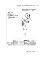
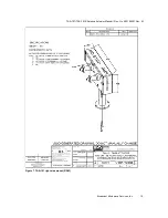
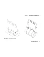
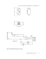
The Cross Tube Strut Mount (Figure 19) has two hinged clamps that can be secured to a single cross-
tube strut. Three diameter sizes are available:
•
P/N 810140225 – 2.25” dia.

