TAA-101/TAA-101S Antenna Actuator Manual | Doc. No. 605169301 Rev. M
Broadcast Microwave Services, Inc.
23
•
P/N 810140250 – 2.50” dia.
•
P/N 810140260 – 2.60” dia.
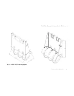
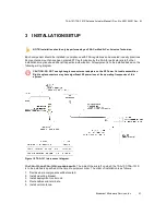
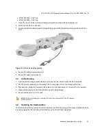
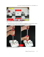
1. Orient the mount so the antenna will deploy straight down (the notches are facing up).
2. Attach the top clamp to the strut.
3. Loosen the bottom clamp support and adjust the angle so that the bottom clamp mates up with the
strut.
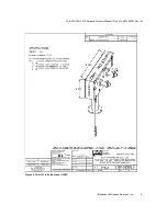
Figure 19. Cross-tube mount assembly
4. Secure the bottom clamp to the strut.
5. Secure the upper clamp support.
3.3
Cable Routing
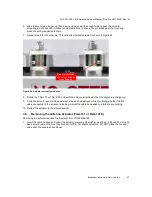
1. Now that the Mounting Bracket has been installed, the final cable lengths can be determined.
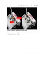
2. Set the actuator assembly on the bracket. Do not snap the unit into the bracket at this time.
3. Proceed with routing the Power and RF cables from their destinations in the aircraft to the actuator.
4. Place grommets around any hole drilled to prevent cable damage.
5. Secure cables every 6 to 12 inches.
NOTE: Maintain signal integrity by minimizing the losses due to sharp bends in the RF cable and
90
°
RF connectors.
3.4
Installing the Up/Down Box
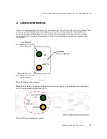
The Up/Down Box is mounted to the center console or cyclic control using Velcro strips. It is positioned so
it is easily viewed by the pilot and will not interfere with normal in-flight operations.

