TAA-101/TAA-101S Antenna Actuator Manual | Doc. No. 605169301 Rev. M
Broadcast Microwave Services, Inc.
iii
Contents
1
INTRODUCTION ................................................................................................................................................... 1
2
SYSTEM DESCRIPTION ...................................................................................................................................... 2
2.1
TAA-101 and TAA-101S Components and Accessories ............................................................................... 5
2.2
Technical Specifications ............................................................................................................................... 8
3
INSTALLATION/SETUP ..................................................................................................................................... 21
3.1
Deciding the Component Locations ............................................................................................................ 22
3.2
Installing the Mounting Bracket ................................................................................................................... 22
3.3
Cable Routing ............................................................................................................................................. 23
3.4
Installing the Up/Down Box ......................................................................................................................... 23
3.5
Cable Termination ...................................................................................................................................... 24
3.6
Antenna Installation .................................................................................................................................... 24
3.7
Installing the Antenna Actuator (TAA-101 or TAA-101S) ............................................................................ 24
3.8
Removing the Antenna Actuator (TAA-101 or TAA-101S) .......................................................................... 27
4
USER INTERFACE ............................................................................................................................................. 29
5
OPERATION ....................................................................................................................................................... 30
6
PREVENTIVE MAINTENANCE .......................................................................................................................... 31
6.1
Maintenance Schedule ............................................................................................................................... 31
6.2
Maintenance Procedures ............................................................................................................................ 31
7
WARRANTY ....................................................................................................................................................... 33
7.1
Customer Service Information .................................................................................................................... 33
8
TROUBLESHOOTING ........................................................................................................................................ 34
8.1
Connector Pin-outs ..................................................................................................................................... 34
List of Figures
Figure 1. Cross-tube strut mount.................................................................................................................................... 3
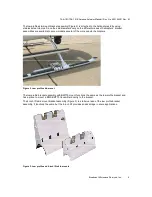
Figure 2. Low profile skid mount .................................................................................................................................... 4
Figure 3. Low profile and 4-inch lift skid mounts ............................................................................................................ 4
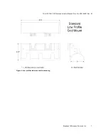
Figure 4. Low profile skid mount outline drawing ........................................................................................................... 7
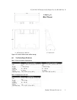
Figure 5. Four-inch lift skid mount outline drawing ......................................................................................................... 8
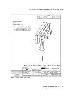
Figure 6. TAA-101 left side mount (LSM) ....................................................................................................................... 9
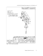
Figure 7. TAA-101 right side mount (RSM) .................................................................................................................. 10
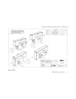
Figure 8. TAA-101S ..................................................................................................................................................... 11
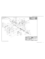
Figure 9. TAA-101, left side, exploded view ................................................................................................................. 12
Figure 10. TAA-101 outline drawing ............................................................................................................................. 13
Figure 11. Weldment, Hughes 300, skid mount, low profile omni deployment ............................................................. 14
Figure 12. Bell 412 with 4.0" lift skid mount, weldment ................................................................................................ 15
Figure 13. TAA-101 retract/deploy switch schematic ................................................................................................... 16
Figure 14. Typical wiring, TAA-101 in analog application ............................................................................................. 17
Figure 15. Up-Down Box deployment control (analog) ................................................................................................. 18
Figure 16. Typical wiring, TAA-101 in digital application .............................................................................................. 19
Figure 17. TAA-101 drag vs. speed graph ................................................................................................................... 20
Figure 18. TAA-101 interconnect diagram ................................................................................................................... 21
Figure 19. Cross-tube mount assembly ....................................................................................................................... 23
Figure 20. Actuator Installation and Removal tools ...................................................................................................... 25
Figure 21. Position of detent pins ................................................................................................................................. 25
Figure 22. Aligning the actuator (sealed actuator shown) ............................................................................................ 26
Figure 23. Using the actuator installation tool .............................................................................................................. 26
Figure 24. Actuator correctly mounted ......................................................................................................................... 27
Figure 25. Using the actuator removal tool on forward and rear pins ........................................................................... 28
Figure 26. Up/Down Box interface ............................................................................................................................... 29
Figure 27. Alternate deployment control ...................................................................................................................... 29
Figure 28. Product label ............................................................................................................................................... 33


