TAA-101/TAA-101S Antenna Actuator Manual | Doc. No. 605169301 Rev. M
Broadcast Microwave Services, Inc.
2
2 SYSTEM DESCRIPTION
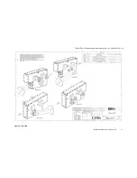
The TAA-101 and TAA-101S Antenna Actuator Assemblies consist of the Antenna Actuator that deploys
the antenna; a Bracket Mount Assembly used to attach the Actuator to the Helicopter; the Up/Down Box
to control the actuator; and the interconnection cables.
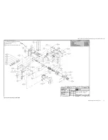
The main components of the Antenna Actuator are a gear head motor, worm and worm gear assembly.
The gear head motor is pinned to the worm and drives the worm gear when the motor is energized with a
24 to 32 volt dc signal. The motor/worm combination in turn drives the worm gear assembly. The polarity
of the dc signal determines the direction that the motor turns. Therefore, connecting dc of one polarity will
deploy the antenna, and reversing the polarity will stow the antenna. At both ends of the travel of the
worm gear, a roll pin in the side of the worm gear actuates a limit switch. When the switch is opened the
power to the motor is disconnected and the unit will remain in this position until a command is given
(reversed polarity voltage) to move in the opposite direction. The worm/worm gear combinations are of
the type that cannot be back driven; therefore power is not required to maintain the position of the
antenna. The Antenna Actuator is available in sealed and non-sealed versions as well as configurations
for left or right side mounting depending on the application.
The Antenna Actuator Assembly has two hardened steel pins on the side of the unit, which snap into
sockets on the Bracket Mount Assembly. The Bracket Mount Assembly has spring-loaded release pins
that retain the Antenna Actuator Assembly. This is to provide a weak link to protect the aircraft in the
event the helicopter is landed with the antenna deployed. The release pins allow the Antenna Actuator to
detach to prevent damage to the helicopter.
CAUTION: Landing with the antenna deployed will damage the antenna.
When the actuator is in the stowed position the omni is parallel to the skid and above ground level and
does not interfere with take off or landing of the helicopter.
There are several types of Bracket Mount Assemblies depending on the application. This document
applies to the cross tube strut mount and skid mount assemblies:
•
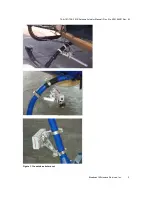
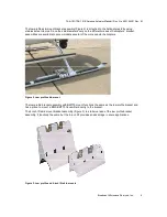
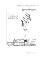
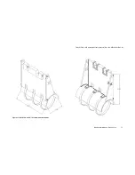
a cross-tube strut mount bracket assembly (Figure 1):
o
P/N 810140225 – 2.25” dia.
o
P/N 810140250 – 2.50” dia.
o
P/N 810140260 – 2.60” dia.
•
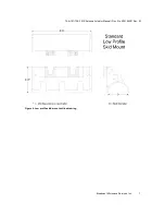
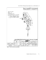
a low profile skid mount bracket assembly;
•
a low profile skid mount bracket assembly with BMT75 mount;
•
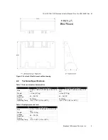
a 4-inch lift skid mount bracket assembly.
The cross-tube strut mount bracket assembly (Figure 1) attaches to the struts of the helicopter.


