OZONE ANALYZER BMT 964 Manual, Rev. 04/2021
7
3
Installation and Power Connection
The OZONE ANALYZER BMT 964 is a 144 x 72 mm front panel instrument (according to
DIN 43700). The mounting cut-out should be 139 x 67 mm (W x H). Depth is approx. 230 mm.
The power line voltage may be 100 to 240 VAC (50 or 60 Hz). All necessary parts needed for
installation are supplied with the instrument (e.g. power and signal connectors, mounting brack-
ets, a tool for opening the sample gas filter holder). The serial port cable is a standard RS-232
type and is supplied with every analyser (also with the different models in the Appendix).
The installation of the power connector has to be made by a person aquainted with the
safety problems involved. Do not connect or disconnect the voltage-carrying connector!
Warning:
This product relies on the building's installation for short-circuit (overcurrent) protec-
tion. Ensure that a fuse or circuit breaker no larger than 15 A at 120 VAC (10 A at 240 VAC) is
used on the phase conductor.
The power receptacle or the mains socket-outlet the instrument is connected to should be easily
accessible for fast interruption of power, or other means for switching off power should be pro-
vided.
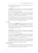
Optionally the instrument is available in a low voltage version with a voltage range from
12 to 36 VDC (max. power consumption is 15 W). The backplane is shown here:
For the sample gas connection 3 x 5 mm PTFE tubing (or FEP tubing 1/8" x 3/16") should be
used (which we will supply on request). The sample gas has to be connected via the sample gas
filter ("IN"). The time lag of the concentration measurement depends on
a) the flow rate of the sample gas,
b) the length of the tubing to the analyzer,
c) the cross section of the tubing (we recommend tubing 3 x 5 mm, not more!),
d) the time lag of the analyzer itself. At the recommended flow rate of .2 to 1 l/min time lag will
be 2 to 0.4 s with a 3 x 5 mm tubing length of 1 m.

