OZONE ANALYZER BMT 964 Manual, Rev. 04/2021
9
4
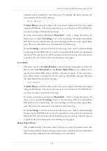
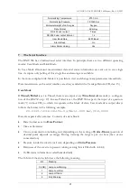
Output and Control Terminals
All signal leads should be shielded. The shield should be connected to the ground terminal ( )
of the instrument via an 1/4'' FASTON connector. The following table describes the signal con-
nector and is also printed onto the top of the standard instrument.
Analog Outputs
The output signals are updated about 25 times per second.
The voltage output is an isolated voltage signal 0 to 10 V, proportional to the concentration (ac-
tually this signal swings down to about -0.25 V below zero). Input resistance of the load should
be higher than 1 k
.
The current output is an isolated current signal 4 to 20 mA, proportional to concentration (with
an offset of 4 mA). Input resistance of the load should be less than 600
(optional 1350
).
The current output provides the energy for the curent loop.
Attention:
The current output must not be connected to an external power supply
!
Binary Input
The binary input is used to trigger the ZERO function of the OZONE ANALYZER BMT 964.
By applying a voltage of typ. +24 VDC between pin 11 (+) und pin 10 (-) for about 0.5 seconds
the instrument will be zeroed.
The ZERO function may be triggered only after complete
purging of the cuvette with filtered air or oxygen
(purging for at least 10 seconds plus delay
of the input tubing)!
OZON E AN AL Y ZER BMT 964
BMT MESSTECHN IK, BERLIN phone + + 49 30 - 801 85 95 fax + + 49 30 - 802 23 62
OSTI, MONTEREY, CA phone + + 1 - 831 - 6491141 fax + + 1 - 831 - 6491151
OUTPUT AN D CON TROL TERMIN ALS
AN ALOG OUTPUTS:
Isola ted
7 Concentration 0- 10V
6 GN D (10 V)
5 Concentration
4- 20 mA
4 GN D (4- 20 mA)
ERROR RELAY:
Isola ted, U
ma x
= 30 V DC, I
ma x
= 1 A
1
3
RELAY CONTACTS:
OUTPUTS:
Isola ted, U
ma x
= 28 V, I
ma x
= 0.5 A
8 Out Common
9 La mp Low
12 High Ala rm
13 Low Alarm
14 Cuvette Dirty
2 Purge
IN PUT:
Isola ted, U = 24 VDC, I = 18 mA
10 Zero GN D
11 Set to Zero (no O
3
)
USE SHIELDED CABLE CON N ECT SHIELD TO
ALWAYS CON SULT THE MAN UAL
Open on Error

