background image


BMM

®

 System

 Manual 

– Monitoring Procedures 

15 


www.bmt.com.au 

a)


Turn on the 

Remote Processing Module


(RPM)

 by pressing the button on top of the unit. 

b)


Turn 

on the 

Controller

 by pressing the 

Power

 button. 


Select the “Blast Name” from the pull down menu.  


Select 

Detect. 


c)


Set the range to a suitable value – usually 8-10. 

d)


Select the BMM

® 

colour that you are searching for. This information is contained on the 

blast plan created during installation. 


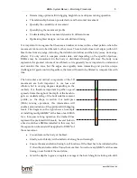
As  a  general  rule,  start  a  search  by  walking  along  a  slope,  i.e. 
approximately  constant  elevation  rather  than  up  or  down  a  slope. 
More  area  can  be  scanned  in  a  short  time  because  it  is  slow  to 
“staircase” up and down a slope. Once the maximum is found along 
the slope, you will only have to go up or down once to get close to the 
peak. 


e)


Find a BMM

® 

signal. 

o


Before you can pinpoint a BMM

®

, you have to get within range. Therefore, your 

initial objective is to just locate a signal.  

o


You will not pick up a signal until you are within about 15 - 20 m of the BMM

®


so keep this in mind when planning your search path.  

o


To quickly locate the general vicinity of a BMM

®

, walk an approximately straight 

line and approximately constant elevation if possible (e.g. along a slope rather 
than up it), towards where you think a BMM

®

 will be (or was).  

o


The signal strength will rise very quickly as you approach the BMM

®

, unless it 

is close to the limit of the 

Detector.


f)


As you get closer to the signal, it will probably be 
necessary to 

decrease the range

 to maintain the 

signal  at  a  level  that  does  not  overload  the 
detector. 

g)


 BMM

® 

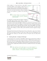
Signal located 

o


When  a  signal  is  detected,  keep  going 
straight  in  that  direction  until  the  signal 
decreases.  

o


Always

 walk 2-3 m 

past

 this first peak to 

be  sure  it  is  not  the  “phantom  peak” 
(discussed in Section 4.6). 

o


Back  up  to  about  where  the  maximum 
was.  You  are  now  at  location 

  in  the 

diagram to the right.  

3D Surface Plot (Survey Points in Results - Survey Both.stw 4v*98c)

mV = Distance Weighted Least Squares

 250 
 200 
 150 
 100 
 50 
 0 
 -50 

Summary of Contents for Blast Movement Monitor

Page 1: ...BMM System Manual Monitoring Procedures Solutions to Reduce Ore Loss and Dilution ...

Page 2: ...oring Hole Diameter 7 3 BMM Installation ___________________________________________________________7 3 1 Introduction 7 3 2 Installation Procedure 8 3 3 Delayed Start 10 3 4 Wet Holes 11 3 5 Test Button on the Activator 12 4 BMM Detection ____________________________________________________________13 4 1 Introduction 13 4 2 Orientation of the Detector 13 4 3 Detecting Procedure Locating the Peak ...

Page 3: ...ion and experience are the greatest assets for any practical activities For example it would be very difficult to learn to ride a bicycle by reading a manual because there is no sensory experience Similarly a new BMM System operator needs to get a feel for what the changing signal strength is indicating and how to move the Detector This can only be obtained by actually doing it This manual does no...

Page 4: ...r as the depth increases and therefore is harder to locate and requires greater separation from BMM s of the same colour Concentrate at about mid bench to begin with before investigating the movement in other parts of the bench The exception to this is for multi pass flitch mining where it is important to monitor different levels The number of BMM s installed depends on many factors but the primar...

Page 5: ...ed dots are the pre and expected post blast BMM locations respectively 2 3 BMM Location for Grade Control When planning the location of BMM s specifically for the purposes of grade control think ahead to what will be critical for translating the ore polygons The main aim is to locate the BMM s as close as possible to the ore boundaries to reduce the error associated with interpolating the ore is t...

Page 6: ... be near it install a BMM inside the ore polygon so all edges are similar distance from that vector 7 Polygon boundaries that are oblique to expected movement are more important than parallel boundaries 8 Concentrate most of the BMM s in the body of the blast away from edge effects unless there is an important ore boundary close to an edge 9 Survivability of the BMM s Install halfway between blast...

Page 7: ...egardless the data will need to be filtered to compare like with like The horizontal and vertical components of the 3D movement are both important to ore loss and dilution but to varying degrees depending on the orebody It is therefore important to gather a good spread of data throughout the depth of the bench to gain an understanding of the horizontal movement profile i e the shape in section For...

Page 8: ...riability within a blast the following guidelines are recommended All monitoring holes within the body of the blast Install the BMM s at the same depths in every hole use multiple BMM s per hole as required Conduct a number of blasts to quantify variability at different depths at least one in the stemming and explosive zones respectively Depending on the scope of the study it may be advantageous t...

Page 9: ...ring holes within the blast pattern 2 6 Monitoring Hole Diameter The BMM s are 98 mm diameter so it is possible to get them into a 102 mm 4 hole but only if the ground is competent and the hole is clean The minimum recommended hole diameter for effective installation is 115 mm 4 5 3 BMM INSTALLATION 3 1 Introduction Installation of the BMM s is arguably the easiest of the monitoring tasks and with...

Page 10: ...ot be switched off once activated with the BMM On button The Detector will be affected by electromagnetic interference from certain equipment and vehicles This usually manifests as unusually erratic signal strength noisy and or elevated signal strength on the Detector There is a usually little interference once in the pit unless a source is close to the Detector Known sources in the pit include su...

Page 11: ... Colour of the BMM to be placed in the hole Measured depth f Turn on the BMM Activator by pressing the Power button If no Delay time delayed start up is required leave display zero If delayed start up is required please consult the applicable BMM Activator Manual for instructions If the delayed start up is selected when the BMM is turned on it will transmit for 15 minutes before going to sleep giv...

Page 12: ...al With experience you will know approximately what the range should be at various depths For example if the hole is 8 m deep and the display is showing Range 3 then the BMM is not at the bottom of the hole or a BMM in the bucket is transmitting If the display is static on Range 1 then the Controller and or RPM may be locked and need to be reset If it is displaying Range 12 then the BMM is probabl...

Page 13: ...d start up the BMM s can be installed on the morning of the blast with an appropriate delay to wake up the following morning when they can be located This scenario would be used if there are underground workings that must settle for a period before accessing the muckpile 3 4 Wet Holes Some special procedures are required when installing BMM s into wet holes to ensure the BMM sinks to the desired d...

Page 14: ...ed backfill the monitor hole as per standard procedures If the water is very muddy drop 1 2 additional suitable sized rocks into the hole prior to backfilling with stemming to ensure the BMM stays at the bottom of the hole 3 5 Test Button on the Activator Test should not be used under normal circumstances The only function it does is check that a BMM will switch on it does not perform any addition...

Page 15: ... signal then you probably haven t Following is a list of things to keep in mind when conducting a search a Where do you expect the BMM s to be Use your plan from the installation stage nd there is also a GPS low precision map accessible on the detector b What signal strength do you expect If you have been locating other similarly installed BMM s on say Range 5 and you think you are close to the BM...

Page 16: ...ft The signal should increase at least initially so continue until you either hit the face with the coil again or it begins to decrease If the signal did not increase then the peak may be close to the previous step so move half the distance down the slope and sweep to locate the peak Clearly this is more challenging and will take longer than working on a flat surface so take your time and check th...

Page 17: ...objective is to just locate a signal o You will not pick up a signal until you are within about 15 20 m of the BMM so keep this in mind when planning your search path o To quickly locate the general vicinity of a BMM walk an approximately straight line and approximately constant elevation if possible e g along a slope rather than up it towards where you think a BMM will be or was o The signal stre...

Page 18: ... Detector displays Please wait A different tone will sound when complete l Mark the location with a suitable marker stake flag paint etc and write the BMM letter from the Detector on the marker This letter must be recorded when the point is surveyed m Repeat until all transmitting BMM s have been located one or more may fail during the blast n Switch the Controller and RPM off when complete the da...

Page 19: ... the graph and hence make the peaks more obvious This will be necessary for deeper BMM s weaker signals o Set the graph to be full screen shown here by touching the graph o Zoom into the top of the red signal There are four zoom levels accessed by pressing 5 on the keypad The Range will be highlighted while zoomed Press 0 on the keypad to return to normal 4 5 Validating the Peak As stated previous...

Page 20: ...tom peak for the real one and it is important for new users to be able to know when they on the phantom peak rather than the real peak because it can waste a lot of time and potentially mark the BMM in the wrong location With experience it is relatively easy to identify this scenario but will catch inexperienced operators particularly if the muckpile is steep and or rough The phantom peak is chara...

Page 21: ...en working on slopes start the search by walking along the slope at approximately constant elevation and the first maximum signal will determine where to begin going up or down the slope which is slow due to the staircase technique Section 4 2 If feasible be above the BMM see diagram at right because the signal can be unusual when at a similar elevation as the BMM Start searching for a new BMM wit...

Page 22: ...eases as the distance from the transmitter increases This relationship is used to calculate the post blast depth of the BMM from the measured signal strength The measured signal strength will be affected primarily by Detector Transmitter Rock type the difference between rock types at a site is usually relatively small except if there are iron rich minerals Electromagnetic interference normally not...

Page 23: ...uding heave the depth can still be calculated albeit with a very small decrease in the accuracy The Depth Calculation algorithm can project beyond the measured calibration set or another larger calibration set can be used 5 3 Using the Data The Depth Calibration data is used in the BMM Explorer software to calculate the post blast depth of each BMM Refer to the software manual for more information...

Page 24: ...ace up safety boots with good ankle support is especially important when walking on the post blast muckpile Drills or other noisy equipment will often be nearby so hearing protection may also be required Follow the site procedures for accessing a blast pattern especially if explosive loading has commenced If the monitoring holes are backfilled manually use correct shovelling technique to avoid bac...

Page 25: ...BMM System Manual Monitoring Procedures 23 www bmt com au ...

Page 26: ... the following two conditions 1 These devices may not cause harmful interference and 2 These devices must accept any interference received including interference that may cause undesired operation Changes or modifications not expressly approved by the manufacturer could void the user s authority to operate the equipment DISCLAIMER Every effort has been made to ensure the procedures set out in this...

Page 27: ...Blast Movement Technologies PO Box 73 Bellbowrie Qld 4070 AUSTRALIA CONTACT DETAILS www bmt com au Phone 61 0 7 3202 9499 Fax 61 0 7 3202 9472 Email office bmt com au ...

Reviews: