background image

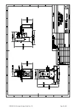
SRS:200:FA-V3 Automatic Seamer. Delta. Rev 1.10

Page 32 of 60

Summary of Contents for SRS:200:FA-V3

Page 1: ...INSTRUCTION MANUAL SRS 200 FA V3 Automatic Round Can Seamer BUBBER MACHINE TOOLS SRS 200 FA V3 Automatic Seamer Delta Rev 1 10 Page 1 of 60 ...

Page 2: ...rea as depending on climatic conditions there can be heat build up in the Motor and Control Panel 3 Ensure that there is no possibility of water or other liquids entering the Motor or Control panel unit solenoid vales and other electricals as this will cause the machine to malfunction components and pose a risk of electrical shock or short circuit 4 Care should be taken when handling the Proximity...

Page 3: ... all work on 24VDC which is derived from the single phase connection through a power supply unit located in the panel 5 Connect all connectors 3 in total from the Control Panel to the appropriate connectors on the machine Another single separate cable from the Panel is to be connected to the Servo Motor lead 6 IMPORTANT The Seaming head must rotate in the direction shown by the Arrow label on the ...

Page 4: ...RESETTING HOME POSITION When the Home Icon is pressed the Indexer rotates slowly to find the Home position This is achieved by means of a Key and Proximity sensor located below the table When the Sensor switches ON the Home position is set The Home position has been factory Set and does not need to be altered or changed unless it is moved In the event that the home position is disturbed Can is not...

Page 5: ...e Position station on the Indexing Wheel as marked above Position the indexer such that the Can is before the seaming station k Power ON the machine and press the Home Position Icon The Indexer should slowly move forward and stop at its Home Position with the Can directly below the seam station l Raise the Can up using the Controller and check for alignment If OK the machine is ready to operate If...

Page 6: ...1 P3 and the Seam operation begins refer to the section on Roller setting to understand the operation Note After engaging the clutch the pneumatic cylinder retracts It does not need to hold the Clutch in the engaged position The clutch disengages mechanically after the Seam cycle is completed 2 After Seaming is completed the clutch disengages The Limit Switch Figure 1 L3 at the rear is pressed to ...

Page 7: ...al Seam after which the clutch disengages The quality of the seam depends mainly on the Seaming rollers and their setting Please carry out the settings as described below Also refer to the Video guide provided for setting the Rollers 1 Pressure Setting To adjust the pressure of the rollers the seaming arm lever SA 49 must be moved inwards or outwards To do so loosen the bolts on the Cam Follower L...

Page 8: ...e same time when adjusting the roller pressure Can Height Setting The machine can accommodate various Can heights within permissible limits To change the height the entire Seaming head assembly has to be moved upwards or lowered as required This is done by loosening the bolts on the adjustment slides SAV 167 and turning the Height Adjustment Wheel SAV 79 to raise lower the head assembly Refer Figu...

Page 9: ...nd no adjustments are required unless there is a change in dimensions Note that the Lid Separator Feeder are highly sensitive to dimensional variations All dimensions are to be maintained within 0 10mm of the original Any deviation may cause the Lid Feeder to Jam and malfunction A sensor is provided at the Lid Stack to ensure sufficient lids are always in the stack In the event that the number of ...

Page 10: ...as sufficient Lids at least a few inches above the lid stack sensor 5 The Emergency Switch is not pressed When pressed the Display will be Orange with an Alarm indicating this status 6 To start the machine press and hold the RUN Icon To Stop press the STOP Icon on the Touchscreen Controller 7 Run the machine briefly for a few seconds to ensure that it is running smoothly 8 In the event of a proble...

Page 11: ...ce b Remove the Indexing Wheel c Remove the Guides d Remove the Sensors on the Lid station e Remove the Lid Station f Remove the Seaming Chuck and Ejector g Loosen the Cam Follower Levers SAV 40 and move the Roller levers outwards Then a Put in the new Seaming Chuck and Ejector b Set the Seaming Roller pressure and height c Affix the Lid Seaming Station and Sensors d Affix the Guides e Affix the I...

Page 12: ...tor may press the Emergency Switch This will shut off all electrical supply to the motors and the machine will turn OFF Once pressed the switch gets locked in the OFF position and must be turned to unlock it and pop up to the ON position 4 Servo Motor The Servo Motor gives the drive to the Rotary Indexer It has a very high precision encoder which ensures that the positioning is 100 accurate In the...

Page 13: ...t the machine 3 No Can No Lid System A Lid is dropped by the Lid separator only when a Can is sensed to be brought to the seam station 4 Lid Stack Sensor This sensor checks for the presence of lids in the lid stack When the level of lids goes below the sensor level the Yellow indicator blinks for about 5 seconds after which the machine is shut OFF Replenish the Lid stack and reset by pressing and ...

Page 14: ...vided to all points indicated on the Lubrication Plan 4 Painted parts may be cleaned with Mild Detergent Do not use thinner or other Industrial Cleaners as these may spoil the finish 5 Perfect Seaming Can be achieved by proper maintenance of the machine most importantly the Seaming Rollers and Seaming Chuck 6 Check and tighten all bolts etc every month 7 The FRL unit must be drained of any water a...

Page 15: ...ted Sufficient Oil is present in the Oil reservoir e Guides Adjusted f Sensors Adjusted g Sufficient Lids are present in the Lid Stack of the Lid Feeder h All safety covers closed and safety interlocks activated i Speed of Pneumatic valves is adjusted for smooth running j Emergency switch in OFF position k Sufficient Lids placed in the Stacker l Manually inspect machine for any tools or foreign ob...

Page 16: ...SRS 200 FA V3 Automatic Seamer Delta Rev 1 10 Page 16 of 60 ...

Page 17: ...SRS 200 FA V3 Automatic Seamer Delta Rev 1 10 Page 17 of 60 ...

Page 18: ...SRS 200 FA V3 Automatic Seamer Delta Rev 1 10 Page 18 of 60 ...

Page 19: ...SRS 200 FA V3 Automatic Seamer Delta Rev 1 10 Page 19 of 60 ...

Page 20: ...SRS 200 FA V3 Automatic Seamer Delta Rev 1 10 Page 20 of 60 ...

Page 21: ...SRS 200 FA V3 Automatic Seamer Delta Rev 1 10 Page 21 of 60 ...

Page 22: ...SRS 200 FA V3 Automatic Seamer Delta Rev 1 10 Page 22 of 60 ...

Page 23: ...SRS 200 FA V3 Automatic Seamer Delta Rev 1 10 Page 23 of 60 ...

Page 24: ...SRS 200 FA V3 Automatic Seamer Delta Rev 1 10 Page 24 of 60 ...

Page 25: ...SRS 200 FA V3 Automatic Seamer Delta Rev 1 10 Page 25 of 60 ...

Page 26: ...SRS 200 FA V3 Automatic Seamer Delta Rev 1 10 Page 26 of 60 ...

Page 27: ...SRS 200 FA V3 Automatic Seamer Delta Rev 1 10 Page 27 of 60 ...

Page 28: ...SRS 200 FA V3 Automatic Seamer Delta Rev 1 10 Page 28 of 60 ...

Page 29: ...SRS 200 FA V3 Automatic Seamer Delta Rev 1 10 Page 29 of 60 ...

Page 30: ...SRS 200 FA V3 Automatic Seamer Delta Rev 1 10 Page 30 of 60 ...

Page 31: ...SRS 200 FA V3 Automatic Seamer Delta Rev 1 10 Page 31 of 60 ...

Page 32: ...SRS 200 FA V3 Automatic Seamer Delta Rev 1 10 Page 32 of 60 ...

Page 33: ...SRS 200 FA V3 Automatic Seamer Delta Rev 1 10 Page 33 of 60 ...

Page 34: ...SRS 200 FA V3 Automatic Seamer Delta Rev 1 10 Page 34 of 60 ...

Page 35: ...SRS 200 FA V3 Automatic Seamer Delta Rev 1 10 Page 35 of 60 ...

Page 36: ...SRS 200 FA V3 Automatic Seamer Delta Rev 1 10 Page 36 of 60 ...

Page 37: ...SRS 200 FA V3 Automatic Seamer Delta Rev 1 10 Page 37 of 60 ...

Page 38: ...ther Cans are being introduced to the Machine Menu To Access the Menu Menu Screen Manual Mode Manual mode Screen Auto Mode Machine Run Screen Config Settings Config Screen Inputs Shows Input Status Outputs Shows Output Status Info Machine information Manual Mode Screen Press the buttons to operate the corresponding controls on the machine manually This mode is useful for setup and testing Settings...

Page 39: ...for which the Lid Seperator Cylinder is kept ON Lid Feeder Hold The time for which the Lid Feeder Cylinder is Held Lid Feed Fault Delay The time the system waits to check whether a Lid has been dropped before giving an Alarm notification Lid Seam Pos Fault Delay The time the system waits to check whether a Lid has been deliverd to the Seam Position before giving an Alarm notification Nitrogen ON T...

Page 40: ... Press Next to show list of Check Points Check Points Screen This Screen shows if the machine is RUN in AUTO Mode and one or more Inputs or Outputs is not in the required state CHK will show against those not in their required state Check and remedy before starting the machine EMERGENCY ON Shows when the Emergency ON Button is depressed SRS 200 FA V3 Automatic Seamer Delta Rev 1 10 Page 40 of 60 ...

Page 41: ...ing Remedy the situation and then press RESET Indicated a Servo fault Switch OFF the mains for a minute to Reset Possible causes for this error are 1 Servo Overload Jam etc 2 Voltage Fluctuation 3 Problem with the Neutral and or Earth connections Shows if the machine is RUN with Lower than require Air Pressure Shows when a Can is present in the Output Conveyor past the Output location SRS 200 FA V...

Page 42: ...s screen will show to indicate completion of the set Run Time When a Production Target value has been set this screen will show to indicate completion of the set Production Target SRS 200 FA V3 Automatic Seamer Delta Rev 1 10 Page 42 of 60 ...

Page 43: ...he overlap and Thickness Formula for measuring the overlap is Overlap Cover Hook Body Hook Cover Thickness x 1 1 Seam Width Overlap Cover Hook Body Hook Cover Sheet Thickness x 1 1 Seam Width Seam Width 2 x Cover Sheet Thickness Body Sheet Thickness SRS 200 FA V3 Automatic Seamer Delta Rev 1 10 Page 43 of 60 ...

Page 44: ...t operation seam to correct the defect 1 Tight 1st Operation Seams If the 1st operation seaming is too tight the bottom will have a plane surface and the cover hook will be turned back as indicated CAUSE REMEDY a 1st Operation Roller Pressure too high a Loosen 1st Operation Roller Pressure b 1st Operation Groove profile too narrow b Replace 1st Operation Rollers with ones with wider profiles SRS 2...

Page 45: ...orn out b Replace 1st Operation Rollers with ones with narrower profiles 3 Sharp Seam The Seam has a sharp edge around the internal periphery of the Cover CAUSE REMEDY a 1st Operation Roller is too high or too low in relation to the chuck lip a Maintain the roller lip height at about 0 50mm to 0 80mm above the chuck lip b 1st Operation Roller pressure too high b Reduce 1st Operation Roller Pressur...

Page 46: ... normal due to the excess metal and sealant at that point CAUSE REMEDY a Worn 1st Operation Roller a Replace the worn Roller b Improper cover flange b Rectify the cover flange c Excessive Irregular amount of sealant c Ensure even sealant application d Radius at the corner is less than 15mm d Normal for some droop to appear in this condition SRS 200 FA V3 Automatic Seamer Delta Rev 1 10 Page 46 of ...

Page 47: ... of 3 layers of the Cover and 2 layers of the body The theoretical calculation is Seam Thickness 3 x Cover Sheet Thickness 2 x Body Sheet Thickness However the actual achievable Seam thickness will be higher due to the sealant present and extra metal at the fold An increase of 0 07 to 0 15mm from the theoretical value is acceptable When inspected the ideal finished seam will show sufficient overla...

Page 48: ... the proper size c Chuck Lip Thickness too much c Replace Chuck with proper lip thickness d Worn out 1st Operation Rollers d Replace Rollers 2 Seam too Wide Excessive 2nd Operation Roller pressure causes the metal to stretch forming a very wide seam This reduces the overlap and causes the formation of a bad seam hook CAUSE REMEDY a Worn Loose 1st 2nd Operation Rollers a Replace Rollers b Excessive...

Page 49: ...b Replace with correct rollers 4 Short Cover Hook CAUSE REMEDY a Low 1st or 2nd Operation Roller Pressure a Increase Roller Pressure b Countersink increasing beyond limit thus limiting available metal b Reduce countersink Check chuck and settings c 1st Operation Roller profile wide or worn c Replace Rollers d Insufficient cover flange d Increase the cover flange e Insufficient body flange d Increa...

Page 50: ...ange c Reduce the cover flange d Too much body flange d Reduce the body flange e Insufficient lower lifting pressure e Increase the lifting pressure Notes There are many factors that influence the quality of a good seam In most cases the above guide should assist in solving common seam problems Please contact us if you face a problem not covered above SRS 200 FA V3 Automatic Seamer Delta Rev 1 10 ...

Page 51: ...SRS 200 FA V3 Automatic Seamer Delta Rev 1 10 Page 51 of 60 ...

Page 52: ...SRS 200 FA V3 Automatic Seamer Delta Rev 1 10 Page 52 of 60 ...

Page 53: ...SRS 200 FA V3 Automatic Seamer Delta Rev 1 10 Page 53 of 60 ...

Page 54: ...SRS 200 FA V3 Automatic Seamer Delta Rev 1 10 Page 54 of 60 ...

Page 55: ...SRS 200 FA V3 Automatic Seamer Delta Rev 1 10 Page 55 of 60 ...

Page 56: ...SRS 200 FA V3 Automatic Seamer Delta Rev 1 10 Page 56 of 60 ...

Page 57: ...SRS 200 FA V3 Automatic Seamer Delta Rev 1 10 Page 57 of 60 ...

Page 58: ...SRS 200 FA V3 Automatic Seamer Delta Rev 1 10 Page 58 of 60 ...

Page 59: ...SRS 200 FA V3 Automatic Seamer Delta Rev 1 10 Page 59 of 60 ...

Page 60: ...yon and Silk Mills GT Road Chheharta Amritsar 143104 India Phone 91 183 2258566 2257700 5003687 Fax 91 183 2258158 Email sales canseamers com Web http www canseamers com SRS 200 FA V3 Automatic Seamer Delta Rev 1 10 Page 60 of 60 ...

Reviews: