background image

1

Key points of inspection

1) (Option A) Check if the battery is fully charged, and you can observe the display of the 

central control panel to check whether the voltage is above 12V.
(Option B, Option C) Check if the battery is fully charged, and you can observe the 

display panel of the central control panel to check the voltage is above 6V.

2) Check the power switch, all plugs of the dash receiver under the seat, and the battery 

terminal line are properly inserted.

3) Check whether the circuit of the over-current protector is automatically disconnected 

(When the motorcycle is overloaded and blocked, the circuit of the over-current protector 

will be disconnected to protect the motor, dash receiver and control panel.)

4) Whether the car is stored for a long time without application and the battery is not 

charged on schedule. 

5) If the remote control cannot start the car, please check whether the remote control 

code-matching function is normally operated. 

6) Check whether the remote control battery power is low. 

Check whether the battery power is enough, and charge or replace the battery if not.

Fire danger! The overcurrent 

protection is only limited to 6A.

Fire danger! The overcurrent 

protection is only limited to 8A.

Fire danger! The overcurrent 

protection is only limited to 8A.

II. Components List

1. Car body

2. Windshield

3. Steering 

Wheel

4. Rear-view mirror

5. Hand shank

6. Wheel

(Option A  2PCS)

(Option B, C  3PCS)

7. Driving wheel

(with rubber wheel 

sleeve)

(Option A  2PCS)

(Option B, C  1PC)

8. Seat

9. Seat backrest 

10. Tail wing

11. Front axle frame 

connecting-rod 

12. J-shaped stick

13. Rear wheel axle

18. Rear-view mirror screw

(3 × 12PAB)

4PCS

19. Front axle frame 

connecting rod locknut

(5MM)

2PCS

20. Steering wheel locknut 

(5MM)

21. Charger

22. Remote Control 

(Option A, Optional B)

23. Plastic tube 

(Option B, Optional C)

2

2

2

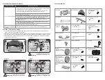
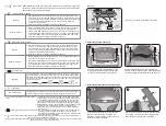
VII. Simple Fault Removal Guidance

Defective conditions

1. The car cannot be started.

2. Music sound is distorted 

or silent

Operation of overcurrent protector 

1) The overcurrent protector is installed under the seat. You can see it by twisting the seat screw off (As 

shown in the figure) and taking the seat away.

2) When the car is overloaded, the overcurrent protector automatically disconnects the circuit (For protecting 

the circuit); when the circuit fault is removed, the overcurrent protector automatically connects the circuit.

3) When the battery has power and the car can not run, please check whether the circuit of the car has an 

open circuit or short circuit.

 (Option A)

Battery black-plug (-)

Black 

cable

Battery 

red-plug (+)

Red cable

Over - current 

protection

Circuit board 

placing box

Warning

 (Option B)

 (Option C)

Battery black-plug (-)

Battery 

red-plug (+)

Red cable

Black 

cable

Over - current 

protection

Circuit board 

placing box

Battery black-plug (-)

Battery 

red-plug (+)

Red cable

Over - current 

protection

Control 

panel box

Warning

Warning

14. Front axle frame 

connecting-rod screw 

(5 × 13PM)

2PCS

15. Steering wheel screw 

(5 × 33PM)

16. Seat and backrest screw

(4 × 15TAB)

(D=7.5)

4PCS

17. Steering gearbox screw

(3 × 10PWAB)

(D=10)

2PCS

Black 

cable

Summary of Contents for M6 GT3

Page 1: ...y to see whether they are jammed by any sundries and to keep their normal lubricating state 3 WARNING WARNING WARNING WARNING To reduce the risk of injury adult supervision is required Strictiy forbidden using on the roadways near motor vehicles slopes swimming pools and where there is water Please wear shoes this toy car can only be used simultaneously by one person Keep away from kids before ass...

Page 2: ...and negative poles of the battery during installation the reverse connection or short circuit of the positive and negative poles of the battery is not allowed to occur 2 Product warning 1 There may be potential sharp edges sharp points or small parts before the assembly of this product and therefore this product shall be assembled by the adult 2 To avoid suffocation keep the plastic bag away from ...

Page 3: ... 3PCS 7 Driving wheel with rubber wheel sleeve Option A 2PCS Option B C 1PC 8 Seat 9 Seat backrest 10 Tail wing 11 Front axle frame connecting rod 12 J shaped stick 13 Rear wheel axle 18 Rear view mirror screw 3 12PAB 4PCS 19 Front axle frame connecting rod locknut 5MM 2PCS 20 Steering wheel locknut 5MM 21 Charger 22 Remote Control Option A Optional B 23 Plastic tube Option B Optional C 2 2 2 VII ...

Page 4: ...earbox hole aligns with the car body axle hole and then insert the rear axle part 13 into the assigned location of the car body Use the thumb to press the center button of the driving wheels part 7 to put them into the rear wheel axle in sequence Steering Wheel Horn button Safety belt Open Open First gear second gear and third gear lamps Forward backward button Left right movement button Sudden br...

Page 5: ...te if no operation occurs within 1 min You can press any button to reawaken it Option A Dashboard lamp Air outlet Central control board Air outlet Option B Option C Central control board Dashboard lamp Option B Option C Installation of rear wheel Front axle 2 Installation of J shaped stick Option A Option B Option C Insert the J shaped iron hook part 12 into the designated gearbox at the front of ...

Page 6: ... USB music will be displayed during USB playback The function icons on both sides of the display are MUSIC USB BT V and the mode or state in which it lies will be displayed by its corresponding icon Four digits display The middle four digits display the voltage of the battery in real time it will display the volume change in adjusting the volume U00 U30 The function icons on both sides of the disp...

Page 7: ...on for the fourth time to turn off both the light and fan and at the same time the green light of this button will be off Press Press Turn on the fan Turn off the light Turn on both the light And the fan Loop It will be as such Press Press Turn on the light Turn off both the light And the fan 6 Light button Option B Option C It is by default in off status press it once the light will turn on and t...

Page 8: ...the front bottom of the car out to pull it away 2 Functions on the central control board Option A Music Light fan Music Previous music volume Voltage display Remote control Foot switch Mode switch USB interface Next music volume One button start main switch Option B Music Music Previous music volume Light button MP3 interface Voltage display Remote control Foot switch Mode switch Next music volume...

Reviews: