2. I N T R O D U C T I O N & S P EC I F I C A T I O N
This air curtain produces an invisible barrier across entrances to commercial premises. It will reduce heating costs and minimise ingress of pollutants.
The air curtain uses any one of our SystemX controllers and up to 11 additional air curtains may be connected together and controlled by one controller.
Controllers allow on/off, high heat/low heat and fan only settings.
All air curtains can be wall mounted or suspended.
3. D E S C R I P T I O N
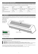
BN Thermic HCA2 air curtains consist of a casing, motor, tangential fan(s), electric heating elements and electronic controller that facilitates the use
of a SystemX controller and the ability to easily daisy chain up to another 11 air curtains. Each air curtain is supplied with a wall mounting bracket as
standard. Casings are finished in durable polyester powder coat. Air is taken through the front input air grille (warmed up if required) and discharged
through the output air grille.
IDENTIFICATION
The
air
curtain
model description is
displayed on a silver
label found inside
the unit casing.
4. M O U N T I N G T H E A I R C U R T A I N
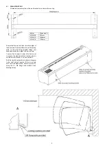
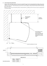
The air curtain can be wall or ceiling mounted at a recommended height of 2.5
– 4m above floor level making sure you leave a minimum of 110mm
from the ceiling to the top of the air curtain.
❑
IMPORTANT!
DO NOT mount air curtain directly below the power isolator.
❑
IMPORTANT!
Ensure that the mounting surface / ceiling supports are capable of taking the weight of the air curtain.
❑
IMPORTANT!
Always mount the air curtain horizontally. Mounting at any other angle will reduce the air curtain
’s life and invalidate the guarantee.
❑
IMPORTANT!
The air intake and output areas must be kept completely clear for a minimum of 1m from the front of the air curtain.
The output grille should be installed as close as possible to the top of the doorway opening to ensure minimal air leakage around the door curtain.
Ideally the air curtain should be a minimum of 100mm wider than the doorway on both sides.
For correct installation and operation, observe minimum spacing to wall and soffit surface shown in diagram to the right.
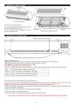
For controllers see section 7
Model
HCA2-09
HCA2-13
HCA2-18
Power (High heat setting)
9kW
13.5kW
18kW
Input supply
400V N Earth
400V N Earth
400V N Earth
Dimensions (W x D x H)
1113 x 265 x 254mm
1621 x 265 x 254mm
2121 x 265 x 254mm
Weight
19.6kg
25.4kg
31.9kg
Recommended Mounting Height
2.5 - 4.0M
2.5 - 4.0M
2.5 - 4.0M
2
Summary of Contents for HCA2 Series
Page 6: ...6 ...


