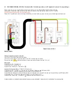
4.3 230V SINGLE PHASE
– With CS-1 Controller (CS-1 Controller provides on / off / high heat / low heat / fan only settings).
Please make sure you have read the Safety instructions and that you are a suitably qualified electrician before continuing.
Drawings show connections inside the black terminal box on the outside of the heater and the inside of the CS-1 Controller.
Do NOT use power tools to undo or do up terminal screws.
Please Note:- Specified cable sizes are for typical installations, correction factors may need to be used when determining actual cable sizes.
Standard Connection using CS-1 Controller
Use 1.5mm² 3 Core Mains Cable (see note above).
Use 1.5mm² 5 Core Cable to connect the heater to the CS-1 Controller (see note above).
Remove any links
that may be present in heater terminal box between terminals 1,2,3,4 or 5.
Mains Cable
Connect Brown wire
– Terminal 1 or L.
Connect Blue wire
– Terminal 5 or N.
Connect Green / Yellow wire
– Terminal E or
Heater to CS-1 Controller Cable
– (Colours for reference only)
Connect Brown wire
– Terminal 1 or L of heater and Top Terminal L (Supply) on right DP Switch of CS-1.
Connect Grey wire
– Terminal 2 of heater and Centre switch Terminal COM of CS-1.
Connect Blue wire (adding red or other suitable colour sleeve to both ends first)
– Terminal 3 of heater and Terminal COM on Left SP Switch of CS-1.
Connect Black wire
– Terminal 4 of heater and Terminal L1 on left SP Switch of CS-1.
Connect Green / Yellow wire
– Terminal E or
of heater and earth connection on CS-1.
PLEASE CHECK ALL CONNECTIONS BEFORE TURNING ON AS INCORRECT WIRING IS NOT COVERED BY THE GUARANTEE


