background image

15

EN

As the user of this product, you are solely 
responsible for operating in a manner that does 
not endanger yourself and others or result in 
damage to the product or the property of others. 

This model is controlled by a radio signal subject 
to interference from many sources outside your 
control. This interference can cause momentary loss 
of control, so it is advisable to always keep a safe 
distance in all directions around your model as this 
space will help avoid collisions or injury.

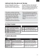
Additional Safety Precautions and Warnings

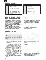
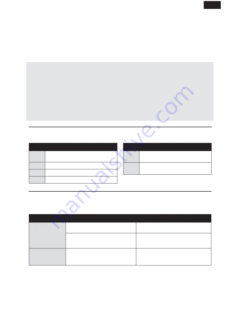
Post Flight Checklist

1.


Disconnect fl ight battery from ESC 


(Required for Safety and battery life).

2.


Power off transmitter.

3.


Remove fl ight battery from aircraft.

4.


Recharge fl ight battery.

5.


Store fl ight battery apart from aircraft 


and monitor the battery charge.

6.


Make note of fl ight conditions and fl ight 

plan results, planning for future fl ights.

• Always keep a safe distance in all directions 

around your model to avoid collisions or injury. 

• Always operate your model in open spaces away 

from full-size vehicles, traffi c and people.

• Always carefully follow the directions and 

warnings for this and any optional support 
equipment (chargers, rechargeable battery 
packs, etc.).

• Always keep all chemicals, small parts and 

anything electrical out of the reach of children.

• Always avoid water exposure to all equipment 

not specifi cally designed and protected for this 
purpose. Moisture causes damage to electronics.

• Never place any portion of the model in your 

mouth as it could cause serious injury or 
even death.

• Never operate your model with low transmitter 

batteries.

Troubleshooting Guide

Problem

Possible Cause

Solution

Control surfaces not 
at neutral position 
when transmitter 
controls are at neutral

Control surfaces may not have been 
mechanically centered from factory

Center control surfaces mechanically by 
adjusting the U-bends on control linkages

Aircraft was moved after the fl ight battery 
was connected and before sensors 
initialized

Disconnect and reconnect the fl ight battery 
while keeping the aircraft still for 5 seconds

Model fl ies incon-
sistently from fl ight 
to fl ight

Trims are moved too far from neutral 
position

Neutralize trims and mechanically adjust 
linkages to center control surfaces

AS3X

Summary of Contents for E-FLITE UMX ASK-21

Page 1: ...Instruction Manual Bedienungsanleitung Manuel d utilisation Manuale di Istruzioni UMX ASK 21 ...

Page 2: ...intenance It is essential to read and follow all the instructions and warnings in the manual prior to assembly setup or use in order to operate correctly and avoid damage or serious injury NOTICE All instructions warranties and other collateral documents are subject to change at the sole discretion of Horizon Hobby Inc For up to date product literature visit www horizonhobby com and click on the s...

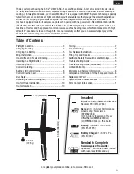
Page 3: ...our product online go to www e fliterc com Table of Contents Preflight Checklist 4 Charging Warnings 4 Charging the Battery 5 Wing Installation 6 Transmitter and Receiver Binding 7 Installing the Flight Battery 7 Initializing AS3X 8 Control Centering 8 Settings for Control Horns 8 Control Direction Test 9 Dual Rates 9 Adjusting Center of Gravity CG 9 Hi Start Hook Installation 10 Hi Start Launch 10 ...

Page 4: ...nd warnings must be followed exactly Mishandling of Li Po batteries can result in a fire personal injury and or property damage By handling charging or using the included Li Po battery you assume all risks associated with lithium batteries If at any time the battery begins to balloon or swell discontinue use immediately If charging or discharging discontinue and disconnect Continuing to use charge ...

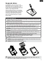
Page 5: ...sually with the label on the battery facing outward to prevent reverse polarity connection However check for proper alignment and polarity before proceeding to the next step 4 Gently press the battery and its connector into the charge jack connector located at the bottom of the slot in the charger 5 When you make the connection successfully the LED on the charger turns solid red indicating chargin...

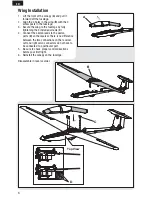
Page 6: ...ly tightening the 4 included screws C 4 Connect the aileron leads to the aileron ports D on the receiver There is no difference between the two connections on the receiver Left and right servo connectors do not have to be connected to a particular port 5 Be sure to check proper control directions before your first flight 6 Reinstall the canopy on the fuselage Disassemble in reverse order A C B D T...

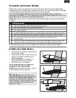
Page 7: ...le trim are in the low position 6 Put your transmitter into bind mode Refer to your transmitter s manual for binding button or switch instructions 7 After 5 to 10 seconds the receiver status LED will become solid indicating that the receiver is bound to the transmitter If the LED does not turn solid refer to the Troubleshooting Guide at the back of the manual For subsequent flights power on the tra...

Page 8: ...r Before the first flights or in the event of an accident make sure the flight control surfaces are centered Adjust the linkages mechanically if the control surfaces are not centered Use of the transmitter sub trims may not correctly center the aircraft control surfaces due to the mechanical limits of linear servos 1 Make sure the control surfaces are neutral when the transmitter controls and trims a...

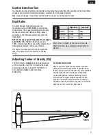
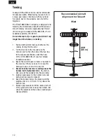
Page 9: ...inear servos to make significant noise The noise is not an indication of a faulty servo Tip For the first flight fly the model in low rate Tip For landing we recommend using high rate elevator Dual Rates High Rate Low Rate Aileron 100 70 Elevator 100 70 Rudder 100 70 Adjusting Center of Gravity CG The CG location is 13mm back from leading edge of the wing at the root This CG location has been determin...

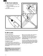
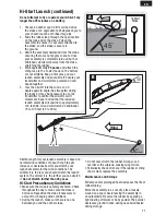
Page 10: ...uded launch assembly On your chosen flying field anchor your launch assembly the furthest point upwind so that you can launch into the wind CAUTION Avoid driving a stake into buried utility lines or damage and injury could result Contact local utility authorities for assistance if needed Tip For your first launches aileron and elevator input should not be necessary and is not recommended Use only the...

Page 11: ...sembly will unwind to approximately 120 feet 36 m and will stretch an additional 75 to 100 feet 23 to 30 m Stretch length for your launch assembly is based on normal wind conditions of about 5 mph 8 kph Increase or decrease how far you stretch your launch assembly for the wind conditions The windier it is the less you should stretch the launch system The calmer it is the further you can stretch it...

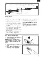
Page 12: ...nway facing into the wind 2 Tie the tow line to the tow plate on the Carbon Cub Tie the other end of the tow line to the release mechanism under the nose of the E flite UMX ASK 21 see tow release installation section 3 Space the aircraft apart so there is no slack in the tow line If there is slack it can result in damage to one or both of the aircraft 4 Ensure that the tow line is resting above the...

Page 13: ...e sailplane becoming unstable If a problem occurs the pilot of the sailplane should release the tow line from the nose of his sailplane so that both aircraft can be safely landed NOTICE Crash damage is not covered under warranty If there is a break in the tow line tie the ends together securely or replace the line EFLU1257 when needed Recommended Aircraft Towing Positions When Flying 28 ft 8 5 m T...

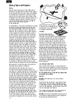
Page 14: ... s heat becoming warm and heating the air above it The heated air rises and forms a column or funnel Usually the base of the thermal is small The updraft expands and decreases in speed as the air rises and cools There are usually downdrafts around the updraft as cooler air falls or moves less than the warm updraft Thermals can vary in strength rising at speeds from a few hundred to over a thousand...

Page 15: ...ay from full size vehicles traffic and people Always carefully follow the directions and warnings for this and any optional support equipment chargers rechargeable battery packs etc Always keep all chemicals small parts and anything electrical out of the reach of children Always avoid water exposure to all equipment not specifically designed and protected for this purpose Moisture causes damage to e...

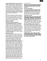
Page 16: ...NTIAL DAM AGES LOSS OF PROFITS OR PRODUCTION OR COMMERCIAL LOSS IN ANY WAY REGARDLESS OF WHETHER SUCH CLAIM IS BASED IN CONTRACT WARRANTY TORT NEGLIGENCE STRICT LIABILITY OR ANY OTHER THEORY OF LIABILITY EVEN IF HORIZON HAS BEEN ADVISED OF THE POSSIBILITY Problem Possible Cause Solution LED on receiver flashes and aircraft will not bind to transmitter during binding Transmitter too near aircraft du...

Page 17: ...d at our facility An Online Service Request is available at http www horizonhobby com content _service center_render service center If you do not have internet access please contact Horizon Product Support to obtain a RMA number along with instructions for submit ting your product for service When calling Horizon you will be asked to provide your complete name street address email address and phon...

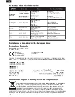
Page 18: ...dom Horizon Hobby Limited Units 1 4 Ployters Rd Staple Tye Harlow Essex CM18 7NS United Kingdom 44 0 1279 641 097 sales horizonhobby co uk Germany Horizon Technischer Service Christian Junge Straße 1 25337 Elmshorn Germany 49 0 4121 2655 100 service horizonhobby de France Horizon Hobby SAS 14 Rue Gustave Eiffel Zone d Activité du Réveil Matin 91230 Montgeron 33 0 1 60 47 44 70 infofrance horizonho...

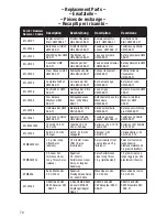
Page 19: ...e Mécanisme UMX ASK 21 Rilascio rimorchio Mechsm UMX ASK 21 EFLU1256 Hardware Set UMX ASK 21 Kleinteile Set Ultra Micro ASK 21 Set de quincaillerie UMX ASK 21 Set accessori di fissag gio UMX ASK 21 EFLU1267 Bare Fuse w Hatch UMX ASK 21 Rumpf mit Haube Ultra Mikro ASK 21 Fuselage nu avec canopy UMX ASK 21 Fusibile con portello UMX ASK 21 EFLB1501S25 150mAh 1S 3 7V 25C Li Po 150mAh 1S 3 7V 25C Li Po ...

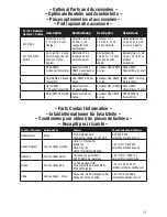
Page 20: ...rteile Piéces optionnelles et accessoires Parti opzionali e accessori Part Nummer Numéro Codice Description Beschreibung Description Descrizione EFLC1004 Celectra 4 Port 1S 3 7V 0 3 A DC Li Po Charger Celectra 1S 3 7V 0 3ADC Li Po Ladegerät mit 4 Anschlüssen Chargeur Li Po CC 0 3 A 3 7V 1S 4 ports Celectra Caricabatterie Li Po 1S da 3 7V 0 3 A CC a 4 porte Celectra EFLC1005 AU EU UK AC to 6V DC 1 ...

Page 21: ...used with permission of Bachmann Industries Inc Futaba is a registered trademark of Futaba Denshi Kogyo Kabushiki Kaisha Corporation of Japan Cub Crafters Carbon Cub associated emblems and logos and body designs of vehicles are either registered trademarks or trademarks of Cub Crafters Inc and are used with permission US D578 146 PRC ZL 200720069025 2 US 7 898 130 Other patents pending www e fliter...

Reviews: