CS6140, CS6140B Series Turning machine Instructions
5-1
5 Machine operation
5.1 Controls
Fig.5-1 shows the location and function of cont rols on machine.
5.2 Method
5.2.1 Drive system
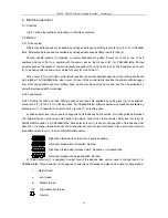
Different spindle speeds are available by setting spindle speed shifting levers (8) and (10). For CS6266B
lathe, different spindle speeds are available by setting spindle speed shifting levers (2) and (3).
24-step spindle speeds of clockwise or counter-clockwise are gotten if Lever (8) is set to one of its 8
positions and Lever (10) to a position with the same color as that of Lever (8). For CS6266B lathe, 24-step
spindle speeds of clockwise or counter-clockwise are gotten if Lever (2) is set to one of its 8 positions and Lever
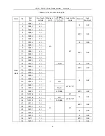
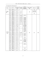
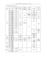
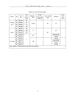
(3) to a position with the same color as that of Lever (2). See Table 5-1.
When Lever (10) is set to the neutral (white) position the spindle will disengage from other driving shafts and
stop rotating. For CS6266B lathe, when Lever (3) is set to the neutral (white) position the spindle will disengage
from other driving shafts and stop rotating. Feed motion also stops at the same time but it can be activated by
using the increased pitch mechanism.
5.2.2 Feed system
5.2.2.1 Setting the pitch and feed: Different pitches and feeds are available by setting lever (6) on headstock,
control knob (7), (9) and (11) on feeding case. For CS6266B lathe, different pitches and feeds are available by
setting lever (1) on headstock, control knob (5), (6) and (7) on feeding case.
a) Feed selector lever (6) is used to change pitch of threads and helix direction, or to change feeds. Because
of a single-direction overrunning clutch fixed in the apron, feed motion is impossible unless lever (6) is set to
RIGHT-HAND position. For CS6266B lathe, Feed selector lever (1) is used to change pitch of threads and helix
direction, or to change feeds. Because of a single-direction overrunning clutch fixed in the apron, feed motion is
impossible unless lever (1) is set to RIGHT-HAND position.
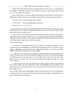
Right-hand thread with normal pitch. Feed is available.
Left-hand thread with normal pitch. No feed.
Right-hand thread with increased pitch. Reduced or increased feed.
Left-hand threads with increased pitch. No feed.
b) Thread selector (7) is designed to select type of threads and also can be used to change feeds. For
CS6266B lathe, Thread selector (5) is designed to select type of threads and also can be used to change feeds.
t
Metric thread
n
Inch thread
m
Module thread
DP
Diametral pitch thread
Neutral
Summary of Contents for CS6140 Series
Page 16: ...CS6140 CS6140B Series Turning machine Instructions 4 3 Fig 4 2 Bearing location diagram ...
Page 31: ...CS6140 CS6140B Series Turning machine Instructions 6 2 Fig 6 1a Location of electrical parts ...
Page 33: ...CS6140 CS6140B Series Turning machine Instructions 6 4 Fig 6 2a Electric schematic diagram 1 ...
Page 34: ...CS6140 CS6140B Series Turning machine Instructions 6 5 Fig 6 2a Electric schematic diagram 2 ...
Page 48: ...CS6140 CS6140B Series Turning machine Instructions 10 2 ...


