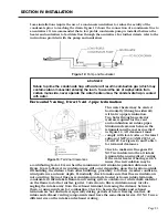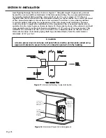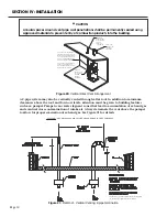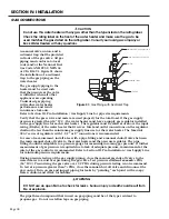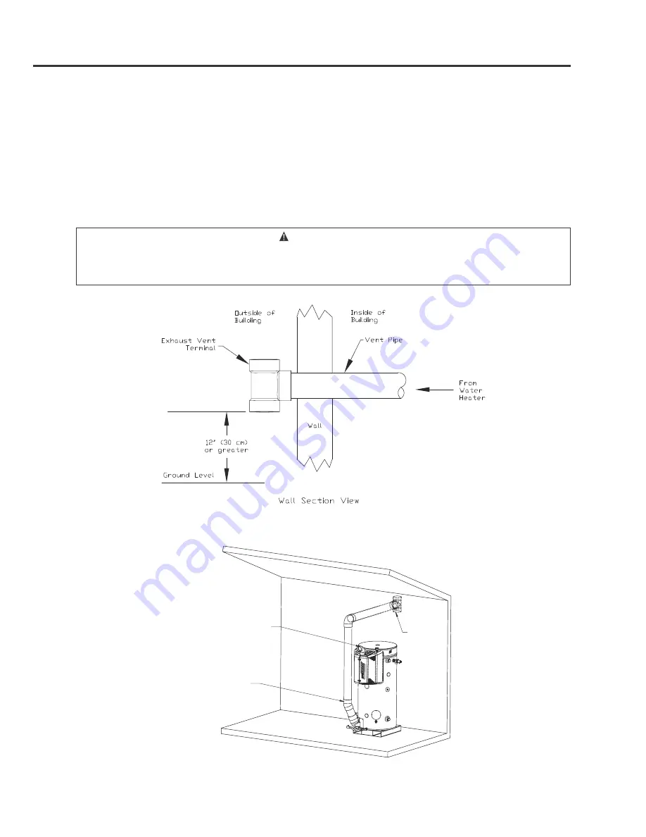
Install piping through the wall as shown in Figure 17. Adequate length of pipe must protrude
beyond the exterior wall for attachment of the termination fitting. The recommended distance
between the terminal fitting and the exterior wall is 1 in. (2.5 cm). A single, 4” 90
°
elbow is
supplied with the water heater for the termination fitting on the air intake. If a screen is preferred
at the exhaust termination, it must have a low resistance to air flow. A screen that significant-
ly restricts airflow will reduce the performance of the water heater and could cause nuisance
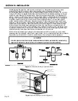
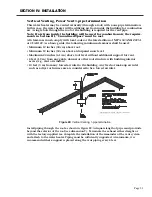
control lockouts. Complete the installation of the remainder of the vent and air intake system
and attach to the water heater as shown in Figure 18. Horizontal sections of the exhaust vent shall
slope upward away from the water heater a minimum of 1/8” per foot (10 mm per meter). This
will allow the condensate in the vent to run back to the condensate drain on the water heater.
Horizontal sections of air intake piping shall slope downward away from the water heater a
minimum of 1/8” per foot.
CAUTION
Annular spaces around vent pipe wall penetrations shall be permanently sealed using
approved materials to prevent entry of combustion products into the building.
Page 28
SECTION IV: INSTALLATION
Figure 17: Horizontal Venting, 1-pipe termination
CONNECT
VERTICAL PIPE TO
(FACTORY
SUPPLIED)
EXHAUST
ASSEMBLY.
TERMINATE
EXHAUST VENT
WITH TEE
(FACTORY
SUPPLIED)
POWER VENT
REQUIRES 4" PVC
ELBOW. (FACTORY
SUPPLIED)
Figure 18: Horizontal Power Vent Arrangement

