background image

20

 D
 GB
 F
 E

96460-05.2022-DGb

5.5  Basic circuit diagram for star-delta start with special motor

* With several connect them in series

Fig. 15

Οnderung

4

0

Datum

Name

Datum
Bearb.
Gepr.
Norm

1

20.02.2009
bauknecht
03.11.2020

Urspr.

2

Ers. f.

3

Ers. d.

4

D/S INT69 HG44/66 neu

5

6

7

BOCK COMPRESSORS

8

=
+

9

Bl.

6.d

Bl.

6.b

6.a

Anschlußkasten Verdichter

BT1

INT69G

DELTA- P II

QA1

L1

L2

L3 N PE

U1

V1

W1

PE

U2

V2

W2

FC1.1

FC1.2

FC2

SF1

BP2

P>

BP3

P

QA2

L1.1

L2.1

L3.1

L1.2

N

PE

BT4

BT2

Θ

11

12

14

L

N B1 B2

12

11

10

9

8

7

6

5

4

3

2

1

Θ

vio

bn

bu

gr

pk

og

Θ

EB1

FC1.1

I>

I>

I>

1

2

QA2

FC1.2

I>

I>

I>

3

4

5

6

1

2

QA4

Y

3

4

5

6

1

2

QA3

D

3

4

5

6

EC1

M

3

˜

QA2

QA2

QA4 KF1

QA4

QA3

KF1

QA3

QA4

KF1

20
21

BT3

Θ

Compressor terminal box

BP2

High pressure safety monitor

BP3

Safety chain (high/low pressure monitoring)

BT1

Cold conductor (PTC sensor) motor winding

BT2

Thermal protection thermostat


(PTC sensor)

*

BT3

Oil temperature sensor

BT4

Release switch (thermostat)

DELTA PII Oil differential pressure sensor DELTA-P II (accessory)
EB1

Oil sump heater

EC1

Compressor motor

Summary of Contents for HGX46 CO2 T

Page 1: ... 4 SH CO2 T HGX46 310 4 ML CO2 T HGX46 310 4 S CO2 T HGX46 310 4 SH CO2 T HGX46 345 4 ML CO2 T HGX46 345 4 S CO2 T HGX46 345 4 SH CO2 T HGX46 440 4 ML CO2 T HGX46 280 MLP 33 CO2 T HGX46 280 SP 46 CO2 T HGX46 280 SHP 46 CO2 T HGX46 310 MLP 37 CO2 T HGX46 310 SP 49 CO2 T HGX46 310 SHP 49 CO2 T HGX46 345 MLP 41 CO2 T HGX46 345 SP 50 CO2 T HGX46 345 SHP 50 CO2 T HGX46 440 MLP 53 CO2 T ...

Page 2: ...turer Contact Read these instructions before assembly and before using the compressor This will avoid misunder standings and prevent damage Improper assembly and use of the compressor can result in serious or fatal injury Observe the safety instructions contained in these instructions These instructions must be passed onto the end customer along with the unit in which the compres sor is installed ...

Page 3: ...uit diagram for part winding start 5 4 Special motor design for direct or star delta start 5 5 Basic circuit diagram for star delta start with special motor 5 6 Electronic trigger unit INT69 G 5 7 Connection of the electronic trigger unit INT69 G 5 8 Functional test of the electronic trigger unit INT69 G 5 9 Oil sump heater 5 10 Selection and operation of compressors with frequency converters 6 Co...

Page 4: ...ng which enable personnel to assemble install maintain and repair refrigeration and air conditioning systems Personnel must be capable of assessing the work to be carried out and recognising any potential dangers DANGER Indicates a dangerous situation which if not avoided will cause immediate fatal or serious injury WARNING Indicates a dangerous situation which if not avoided may cause fatal or se...

Page 5: ...level of knowledge and may change due to further development Legal claims based on the correctness of the information cannot be made at any time and are hereby expressly excluded Compressors with LSPM Motor When the compressor is open there is danger from a strong mag netic field See also Chapter 7 Maintenance These assembly instructions describe the standard version of the compressors named in th...

Page 6: ...n be kept on a relatively low temperature level specially during high load Oil pump independent of direction of rotation for reliable and safe oil supply One decompression valve each on the low and high pressure side which vent into the atmos phere when inadmissibly high pressure levels are reached Oil sight glass Valve plate Cylinder cover Transport eyelet Oil pump Discharge shut off valve access...

Page 7: ...ion speed 11 Displacement 12 Oil type filled at the factory 13 Terminal box protection type Electrical accessories can change the IP protection class Transcritical CO2 version Compressor version Number of poles Swept volume Number of cylinders Size Oil charge Series HG Hermetic Gas Cooled suction gas cooled X Ester oil charge ML Normal cooling and deep freezing at low and medium evaporation temper...

Page 8: ...ssor is possible if overfilled or underfilled Fig 4 Max Min 1 0 Ltr Oil level 3 Areas of application HG 4 6 345 CO2 X 2 4 Type key compressors with LSPM Motor example HG Hermetic Gas Cooled suction gas cooled X Ester oil charge MLP Normal cooling and deep freezing at low and medium evaporation temperatures SP For frequency regulation and extended limits of application SHP For high evaporating temp...

Page 9: ...ation 3 Areas of application 4 Compressor assembly INFO New compressors are factory filled with inert gas Leave this service charge in the compressor for as long as possible and prevent the ingress of air Immediately after refrigeration technological connection of the compressor close the shut off devices in suction dis charge oil return line etc and evacuate the compressor Check the compressor fo...

Page 10: ...for maintenance work Ensure adequate compressor ventilation Do not use in a corrosive dusty damp atmosphere or a com bustible environment F E D C B A 1 2 3 3 2 1 Ra Rz Freigabe Alternativbezug Baumustergeprüft Teil inaktiv Lieferantenzeichnung K Auftrag PL Zeichnung ungültig Entwicklungsstand Teil keine Serie Benzstraße 7 72636 Frickenhausen Germany www bock de Diese Zeichnung ist unser Eigentum S...

Page 11: ...nut are locked Tighten union nut 1 1 2 turns using a spanner wrench The cutting ring is noticeably locked to the socket face for assembly inside pipe connection hold up valve with a spanner wrench This should cause the cutting ring with its cutting edges 1 to cut into the pipe resulting in a visible collar In order to stick to the turns we recommend using marking lines on union nut and pipe After ...

Page 12: ...loss of refrigerant INFO Proper layout of the suction and pressure lines directly after the compressor is integral to the smooth running and vibration behaviour of the system 4 8 Operating the shut off valves Before opening or closing the shut off valve release the valve spindle seal by approx 1 4 of a turn counter clockwise After activating the shut off valve re tighten the adjustable valve spind...

Page 13: ...t The O connection is already available from the factory for the purpose of installing the additional oil level monitoring component Oil should be returned from the oil separator to the compressor via the D1 connection provided for this purpose on the compressor For systems with long pipes and higher degree of contamination a filter on the suction side is recommended The filter has to be be renewe...

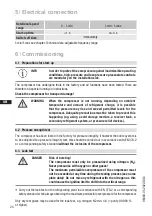
Page 14: ... power supply All protection equipment switching and monitoring devices must comply with the local safety reg ulations and established specifications e g VDE as well as the manufacturer s specifications Motor protection switches are required Motor contactors feed lines fuses and motor protec tion switches must be rated according to the maximum operating current see name plate For motor protection ...

Page 15: ...irect starting YY For part winding start Y YY remove the bridges and connect the motor feed cable according to the circuit diagram 400 V Direct start YY Part winding start Y YY L1 L2 L3 L1 L2 L3 L1 L3 L2 PTC PW II PW I PTC ATTENTION Property damage possible Failure to comply results in reversed fields of rotation and can cause motor damage After the motor has started up with part winding 1 part wi...

Page 16: ... I I QA2 1U1 1V1 1W1 PE EC1 M Y YY 2U1 2V1 2W1 FC1 2 I I I QA3 FC1 1 FC1 2 FC2 SF1 QA2 11 12 14 L N B1 B2 12 11 10 9 8 7 6 5 4 3 2 1 21 20 50 50 Compressor terminal box BP2 High pressure safety monitor BP3 Safety chain high low pressure monitoring BT1 Cold conductor PTC sensor motor winding BT2 Thermal protection thermostat BT3 Oil temperature sensor BT4 Release switch thermostat DELTA P II Oil di...

Page 17: ...69 G KF1 Delay relay for contactor switch over QA1 Main switch QA2 Mains contactor part winding 1 QA3 Mains contactor part winding 2 SF1 Control voltage switch PW INT69 HG44 66 5 6 7 BOCK COMPRESSORS 8 9 Bl 6 d Bl 5 a 2 a DELTA P II BP2 P QA2 BP3 P QA2 KF1 KF1 L1 1 L2 1 L3 1 L1 2 N PE QA3 BT4 BT2 Θ Θ vio bn bu gr Θ EB1 pk og BT3 Θ ...

Page 18: ...18 D GB F E 96460 05 2022 DGb 5 4 Special motor design for direct or star delta start 5 Electrical connection Designation on the name plate Y ...

Page 19: ...tart up is only possible for 230 V power supply Example 400 V Y Direct start only L1 L3 L2 PTC 230 V Δ Direct start Star delta start not on LSPM Motor L1 L2 L3 L1 L2 L3 L1 L3 L2 PTC PTC W2 U2 V2 W1 U1 V1 W2 U2 V2 W1 U1 V1 Only direct start is possible with LSPM Motor ...

Page 20: ... W2 FC1 1 FC1 2 FC2 SF1 QA2 11 12 14 L N B1 B2 12 11 10 9 8 7 6 5 4 3 2 1 FC1 1 I I I 1 2 QA2 FC1 2 I I I 3 4 5 6 1 2 QA4 Y 3 4 5 6 1 2 QA3 D 3 4 5 6 EC1 M 3 20 21 Compressor terminal box BP2 High pressure safety monitor BP3 Safety chain high low pressure monitoring BT1 Cold conductor PTC sensor motor winding BT2 Thermal protection thermostat PTC sensor BT3 Oil temperature sensor BT4 Release switc...

Page 21: ... KF1 Delay relay for contactor switch over QA1 Main switch QA2 Mains contactor QA3 Δ contactor QA4 Y contactor SF1 Control voltage switch D S INT69 HG44 66 neu 5 6 7 BOCK COMPRESSORS 8 9 Bl 6 d Bl 6 b 6 a DELTA P II BP2 P BP3 P L1 1 L2 1 L3 1 L1 2 N PE BT4 BT2 Θ Θ vio bn bu gr pk og Θ EB1 QA2 QA2 QA4 KF1 QA4 QA3 KF1 QA3 QA4 KF1 BT3 Θ ...

Page 22: ...erminals B1 B2 is released by interrupting the supply voltage The hot gas side of the compressor can also be protected against overtemperature using thermal protection thermostats accessory The unit trips when an overload or inadmissible operating conditions occur Find and remedy the cause INFO Connect the trigger unit INT69 G in accordance with the circuit dia gram Protect the trigger unit with a...

Page 23: ...verters the following things must also be observed 1 The maximum permissible operating current of the compressor I max see type plate or technical data must not be exceeded 2 If abnormal vibrations occur in the system the affected frequency ranges in the frequency converter must be blanked out accordingly 3 The maximum output current of the frequency converter must be greater than the maximum curr...

Page 24: ...ever the entire system is to be subjected to a pressure integrity test this should be carried out in accordance with EN 378 2 or a corresponding safety standard without the inclusion of the compressor 6 3 Leak test Carry out the leak test on the refrigerating plant in accordance with EN 378 2 or a corresponding safety standard while always observing the maximum permissible overpressure for the com...

Page 25: ... formation when the system is operating during and after the filling process the shut off point of the low pressure switch should be set to a value of at least 5 2 bar A refrigerant supplement which may become necessary after start up can be topped up in vapour form on the suction side ATTENTION Do not start the compressor if it is under vacuum Do not apply any voltage even for test purposes must ...

Page 26: ... shocks reduced capacity of the refrigerating system WARNING Ensure that both shut off valves are open before starting the compressor ATTENTION If larger quantities of oil have to be topped up there is a risk of oil impact effects If this is the case check the oil return 6 6 Start up Suitably adjusted pressure switches according to EN 378 that switch off the compressor before reaching the maximum ...

Page 27: ...and replace if necessary as during blow off extreme con ditions can occur which may result in a permanent leak Always check system for refrigerant loss after activation of pressure relief valve The decompression valves do not replace any pressure switches and the additional safety valves in the system Pressure switches must always be installed in the system and designed or adjusted in accordance w...

Page 28: ...e system is at a standstill ATTENTION Slugging can result in damage to the compressor and cause refrigerant to leak 6 10 Filter dryer Gaseous CO2 has a significantly lower solubility in water than other refrigerants At low temperatures it can therefore cause blocking of valves and filters due to ice or hydrate For this reason we recom mend the use of an adequately sized filter drier and a sight gl...

Page 29: ...re to prevent oil from exiting with it If the compressor is unpressurized remove the piping on the pressure and suction side e g dismantling of the shut off valve etc and remove the compressor using an appro priate hoist Dispose of the oil inside in accordance with the applicable national regulations When decommissioning the compressor eg for service or replacement of the compressor larger amounts...

Page 30: ... inch ltr ltr 280 4 ML CO 2 T 6 24 40 29 30 380 420 V Y YY 3 50 Hz PW 440 480 V Y YY 3 60 Hz PW PW Part Winding Winding ratio 50 50 59 3 35 5 170 275 20 70 235 22 7 8 28 1 1 8 2 6 2 3 280 4 S CO 2 T 73 0 43 1 196 335 240 280 4 SH CO 2 T 73 4 43 4 196 335 240 310 4 ML CO 2 T 27 20 32 60 66 2 39 8 170 275 235 28 1 1 8 35 1 3 8 310 4 S CO 2 T 81 4 48 4 196 335 240 310 4 SH CO 2 T 82 0 48 8 196 335 24...

Page 31: ...n For 60 Hz operation the specifications have to be multiplied by the factor 1 2 The max working current remains unchanged Take account of the max operating current max power consumption for design of fuses supply lines and safety devices Fuse Consumption category AC3 1 2 4 3 5 All specifications are based on the average of the voltage range For operation with frequency converter see chapter 5 10 ...

Page 32: ...6 25 30 30 30 220 240 V 380 420 V Y 3 50 Hz 265 290 V 440 480 V Y 3 60 Hz 96 3 55 6 35 3 414 239 20 70 235 22 7 8 28 1 1 8 2 6 2 3 280 SP 46 CO 2 T 122 1 70 5 43 0 505 292 240 280 SHP 46 CO 2 T 123 6 71 4 43 5 505 292 240 310 MLP 37 CO 2 T 28 20 33 80 108 7 62 8 39 8 414 239 235 28 1 1 8 35 1 3 8 310 SP 49 CO 2 T 142 0 82 0 48 6 505 292 240 310 SHP 49 CO 2 T 144 0 83 2 49 2 505 292 240 345 MLP 41 ...

Page 33: ...n For 60 Hz operation the specifications have to be multiplied by the factor 1 2 The max working current remains unchanged Take account of the max operating current max power consumption for design of fuses supply lines and safety devices Fuse Consumption category AC3 1 2 4 3 5 All specifications are based on the average of the voltage range For operation with frequency converter see chapter 5 10 ...

Page 34: ...en 0i BS Befestigungsteile aus Lieferumfang entfernt und als Zubehör ergänzt 0i Zubehör DCR22 Heißgastemperatursensor aufgenommen 11181 11372 10670 11460 11595 11614 11643 J Keuerleber C Egeler J Keuerleber J Keuerleber C Egeler A Layh C Egeler 1 über above bis up to Centre of gravity 466 2 0 18 34 0 08 0 150 5 91 403 2 0 15 85 0 08 0 330 12 99 4x 15 0 59 280 11 02 Y B2 E K J1 O A2 B2 B2 I 450 17 ...

Page 35: ...scharge side not lockable 1 8 NPTF D1 Connection oil return from oil separator 1 4 NPTF E Connection oil pressure gauge 1 8 NPTF F Oil drain M22x1 5 I Connection hot gas temperature sensor 1 8 NPTF J1 Oil sump heater 3 8 NPTF K Sight glass 1 1 8 18 UNEF L Connection thermal protection thermostat 1 8 NPTF O Connection oil level regulator 1 1 8 18 UNEF Q Connection oil temperature sensor 1 8 NPTF SI...

Page 36: ... number BC00000A001 BN99999Z999 complies with the following provisions of the above mentioned Directive According to Annex I points 1 1 2 1 1 3 1 1 5 1 3 2 1 3 3 1 3 7 1 5 1 1 5 2 1 5 13 and 1 7 1 to 1 7 4 excepted 1 7 4 f are fulfilled Applied harmonised standards in particular EN ISO 12100 2010 Safety of machinery General principles for design Risk assessment and risk reduction EN 12693 2008 Ref...

Page 37: ...rvice friendly quality products If you have any questions about installation operation and accessories please contact our technical service or specialist wholesaler and or our representative The Bock service team can be contacted by phone 49 0 7022 9454 0 or via service bock de Yours faithfully Bock GmbH ...

Page 38: ...Bock GmbH Benzstraße 7 72636 Frickenhausen Germany Phone 49 7022 9454 0 Fax 49 7022 9454 137 www bock de BOCK Bock GmbH All rights reserved Subject to modifications ...

Reviews: