18
III.12 Repeater for double sided clock
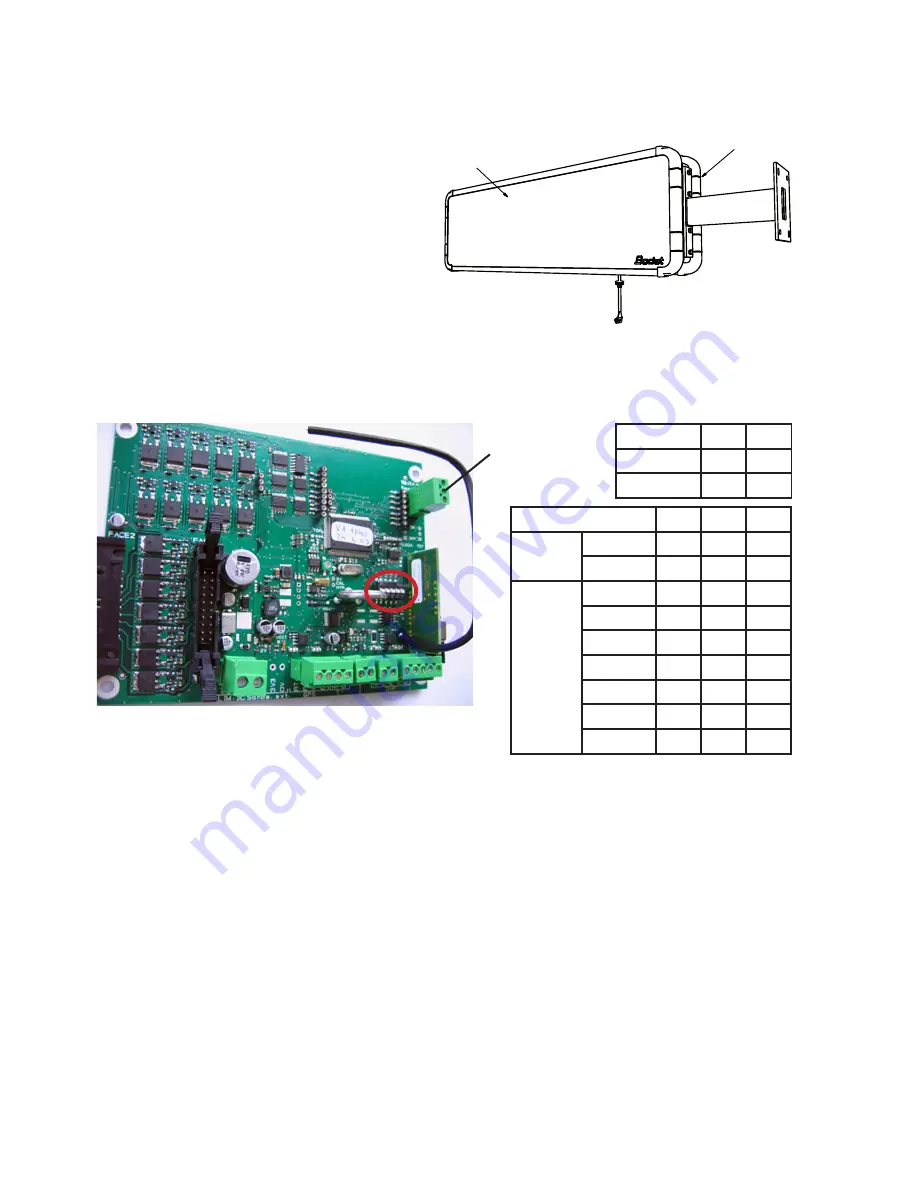
Remove a cable gland M20 on the
master unit, pass the connector of
the repeater through the hole and
put the cable gland back. Plug the
connector of the repeater in the socket
(E) of the master unit card (see “III -
Electrical installation”, page 9).
III.13 Configuration of DIP switches
The DIP switches are set in the factory, but it may be useful when installing
several HMT clocks in series to configure DIP switches 3 to 5.
III.14 Clocks in series
It is possible to connect up to 8 clocks in a serial link.
- Use the DIP switches to program one clock as the master then all the others
as slaves (with a different slave number for each clock). See table above.
- Connect the serial cable on the serial connector of each clock. See
photograph above.
Repeater
Master
Clock type
Dip 1
Dip 2
HMT LED
0
0
HMS LED
0
1
Clock
Dip 3
Dip 4
Dip 5
MASTER
HMT LED
0
0
0
HMS LED
0
0
0
SLAVE
Slave 1
0
0
1
Slave 2
0
1
0
Slave 3
0
1
1
Slave 4
1
0
0
Slave 5
1
0
1
Slave 6
1
1
0
Slave 7
1
1
1
Serial connector


