6
Model
Accessories
Replacement Batteries
Installation Kit
Battery Harnesses
Fuse
Part No.
Quantity
ELI-S-250 & 185
PRT00143
PRT00144
Littlefuse 0312030
PRT00141
1 Required
Battery Maintenance:
The batteries supplied with this equipment require no maintenance. However, the inverter should be
tested periodically, and batteries replaced whenever they will no longer operate the connected fixtures for the rated run-
time. The batteries supplied have a life expectancy of four years when used in normal ambient temperature of 72 degrees F.
Battery Date Code: The battery date code is made up of six characters which represent the month, day and year of manufacture (MM/
DD/YY). For example, 080221 means the battery was made August 2, 2021. There may be additional alpha-numeric characters at the
end of the date code. The date code is located on the battery carton and additionally engraved into the battery.
Battery Replacement:
When replacing batteries, use only batteries supplied by the inverter manufacturer. The old batteries
should be disposed of properly or recycled in accordance with your local regulations. When replacing the batteries, follow
the process outlined in Installation Step #4 and #5 and the cautions and warnings given in these instructions. During
replacement, disable SW-1 on the inverter, then remove AC power from the product.
Fuse:
The fuse contained within this product is field replaceable. For the battery fuse location see illustration 1. To replace
the fuse, disable SW-1 on the inverter then, remove AC power from the product. Ensure that the battery fuse F101 is replaced
by Littelfuse 0312030 (312-030) or equivalent 3AG, 30 A, 32 VDC.
REPLACEMENT PARTS
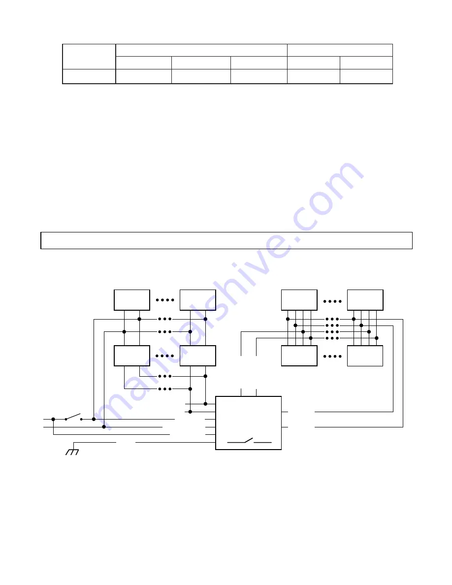
WIRING DIAGRAM
DIMMABLE EMERGENCY LIGHTING SYSTEM
Normal only
Luminaire
Normal only
Luminaire
Normal only
Luminaire
Normal only
Luminaire
Norm/Emer
Luminaire
Norm/Emer
Luminaire
Norm/Emer
Luminaire
Norm/Emer
Luminaire
120 or 277 VAC
Out HOT
Out COM
DIM OUT
+
DIM OUT
-
120 or 277 VAC
Wall Switch
INVERTER
SW-1
Inverter ON / OFF
FGND
UNSW HOT
COM (Neutral)
SW HOT
{
TOTAL DIMMABLE POWER
UP TO 800W
From 0 - 10V
Room Dimmer
DIM IN
+
DIM IN
-
ANY QUANTITY SUPPORTED BY
THE BRANCH CIRCUIT
FIGURE W1
Figure W1
shows an example of a branch circuit powering a number of dimmable luminaires, 4 (or more) of which
are powered through the Emergency Lighting Inverter. During normal AC power mode, the power from the switched
hot lighting power and 0-10V room-dimmer voltage is passed through the Inverter to the “Normal/Emergency”
fixtures. The
un
switched hot charges the battery. During a power failure, the Inverter powers the “Normal/
Emergency” fixtures for a minimum of the products rated runtime at a power level set by the Inverter’s dimming
output circuit. In any example, the
dimmable
“Normal/Emergency” luminaires are automatically limited to
only
draw a total maximum of 250 VA from the ELI-S-250 during an emergency event.


