Step 5b – Connect Remote Control Devices (optional)
The drive can be completely controlled by the keypad and it is recommended that
your operate the inverter this way first to verify that it is operating properly by itself
before proceeding to connect external devices to it. For remote operation, the
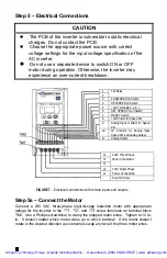
following devices can be connected to terminal block TM2.
FORWARD RUN/STOP SWITCH & REVERSE RUN/STOP SWITCHES
–
To enable these
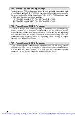
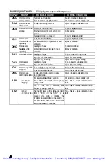
switch inputs, change programmable parameter F10 to “001” (refer to Step 7 for
procedure). Use 20 AWG wire to connect switches with low voltage contacts
between terminals 3 and 5 (FWD) and between 4 and 5 (REV). When the FWD
(or REV) switch is closed, motor will run in forward (or reverse) direction at the
set speed. When the switch is opened, motor will stop. The function of these
switch inputs can be changed with programmable function F03.
PRESET SPEED RUN/STOP SWITCH (SP1)
-
Use 20 AWG wire to connect a switch
with low voltage contacts to terminals 6 and 5. When switch is closed, and when
motor is commanded to run, motor will run at the speed set by programmable
parameter F08. When switch is opened, motor will run at the speed set by either
the keypad or a remote signal. The function of this switch input can be changed
with programmable function F19.
RESET SWITCH (RESET)
-
Use 20 AWG wire to connect a switch with low voltage
contacts to screw terminals 7 and 5 on terminal block TM2. Close the switch to
reset the drive after a fault condition. The function of this switch input can be
changed with programmable function F20.
SPEED SIGNAL INPUT (Vin)
–
To make this input functional, programmable
parameter F11 must be changed to “001” or “002” (refer to Step 7 for
procedure).
Use 20 AWG wire to connect a remote analog voltage or current
signal screw terminal 9 on terminal block TM2, using terminal 10 as the signal
common. The drive will accept a 0 – 10 VDC, 0 – 20 mA, or 4 –20 mA signal
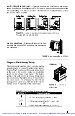
(refer to Step 4 if using a current signal). Alternatively, a speed potentiometer
can be connected to the drive as shown in Fig. 1 with the wiper connected to
terminal 9 and the two end terminals of the speed pot connected to terminals 8
and 10 on the drive.
ANALOG OUTPUT (FM+)
–
This output produces a 0 – 10 VDC signal proportional
to the output frequency of the drive. Use 20 AWG wire to connect a remote
readout or programmable controller to screw terminals 10 and 11 on terminal
block TM2.
FAULT OUTPUT (TRIP RELAY)
–
This relay output has a contact rating of 250 VAC,
1 Amp or 30 VDC, 1 Amp. Use 20 AWG wire to connect a remote device to
screw terminals 1 and 2 on terminal block TM2. The relay is normally open and
closes when there is a fault condition. This can be used to close the circuit of an
alarm or to signal a programmable controller to shut down.
Artisan Technology Group - Quality Instrumentation ... Guaranteed | (888) 88-SOURCE | www.artisantg.com


