LED DISPLAY MESSAGES
–
During most operating conditions, the LED display will
show the output frequency of the drive. There are four special operating conditions
where a text message (b.b., E.S., SP0, and SP2) is displayed to indicate the special
status. There are seventeen text messages that indicate a fault condition when they
are displayed. Some of these messages only occur momentarily because of the
auto-reset feature of the drive. Other messages occur with a shutdown of the drive
and remain displayed until the fault condition is corrected and the drive is manually
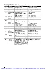
reset. Fig. 13 lists all twenty-one text messages with an explanation of each one
along with any action that may be required when the message is displayed.
FIGURE 13
–
LED display messages and interpretation
DISPLAY
REASON
PROBABLE CAUSE
CORRECTIVE ACTION
b.b.
Base block,
external
An external BASE BLOCK signal was
activated by shorting input terminal 6 or 7 to
12V terminal 5. This requires F19 or F20
to be set at “004”.
N/A – this is a status indication, not a fault
CPF
Program error
Outside noise interference from magnetic
contact
Place an RC surge absorber in parallel
with the magnetic contact
EPR
EEPROM error EEPROM defective
Return the inverter for repair
Pressed
p
or
q
keys when F11 =
“001” or during SP1 operation
Use
p
or
q
keys to adjust frequency
setting only when F11 = “000”
Attempted to modify F29
Do not modify F29
Er1
Error in keypad
operation
Tried to change a parameter that can’t be
changed while motor is running
Change parameter only when motor is
stopped
Er2
Error in parameter
setting
F06 < F07
F06 > F07
E.S.
Emergency stop,
external
An external emergency stop signal was
activated by shorting input terminal 6 or 7 to
12V terminal 5. This requires F19 or F20
to be set at “003”.
N/A – this is a status indication, not a fault
Tried to reverse direction when F22 =
“001”
Adjust F22 to “000”
LOC
Locked motor
direction
Tried to set F22 = “001” when F04 = “001” Adjust F04 to “000”
Power source voltage too low.
Examine power supply
LV
Low voltage while
not operating
Detection circuitry defective.
Return inverter for repair
Power supply voltage too low
Improve power source quality
LVC
Low voltage while
operating
Power supply voltage variation too large Install reactor on power supply input
OC
Over-current at
stop condition
Detection circuit malfunction
Return the inverter for repair
Acceleration time too short
Adjust for longer acceleration time
Improper V/F curve selection
Adjust to a proper V/F curve
OCA
Over-current at
acceleration
Motor to large for inverter
Replace inverter with larger model
OCb
Over-current at
braking
DC Braking frequency, braking voltage, or
braking time too long
Adjust to reduce settings of F15, F16, or
F17
Artisan Technology Group - Quality Instrumentation ... Guaranteed | (888) 88-SOURCE | www.artisantg.com


