Page 3
BRM 3670 Stride Cycle
Page ?
#
Description
#
Description
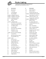
01
Main Frame
35
Nylon Nut (M10)
02
Front Post
36
Bolt Cap (S16 )
03
Front Stabilizer
37
Hex Bolt (M10×50 mm)
04
Rear Stabilizer
38L/38R Left/Right Pedal Hinge Bolt
05L/05R Left/Right Pedal Arm
39
Bushing (
Ф24×20×Ф16.1 )
06L/06R Left/Right Coupler Bar
40L/40R Pedal Connection Joint
07L/07R Left/Right Handlebar
41
Spring Washer (
Φ1
3×B2)
08
Pulse Handlebar
42L/42R Left/Right Nylon Nut
09
Monitor
43
Bolt Cap (S19)
10L/10R Left/Right Pedal
44
Arc Washer (M8, R16)
11
End Cap for Front Stabilizer
45
Carriage Bolt (M8×40 mm)
12
Carriage Bolt (M10×57 mm)
46
End Cap
13
Arc Washer (M10)
47
Foam of Handlebar
14
Cap Nut (M10)
48
Foam of Pulse Handlebar
15
End Cap for Rear Stabilizer
49
End Cap (
Φ2
5
×1.5)
16
Bolt (M8×16 mm)
50
Handle Pulse Wire (Lower)
17
Tension Controller
51
Bolt (M8×30 mm)
18a/18b Main Sensor Wire (Middle)
52
Spring Washer (M8)
19
Tension Wire
53
Cover of Handlebar
20
Main Sensor Wire (Lower)
54
Special Washer (
Φ20)
21
Screw (M5X45 mm)
55
Screw (M4X12 mm)
22L/22R Crank
56
Arc Washer (M8,R25)
23
Bolt Cap (S14 )
57
Bolt Cap (S13 )
24
Hex Bolt (M8×15 mm)
58
Nut (M8)
25
Washer (M8, t2.0)
59
Washer (M5)
26
Bushing (Φ 32×2.5)
60
Cover of Tension Controller
27
Front Post Axle
61
Bushing (Φ14*10*Φ10.1 )
28
End Cap (
Φ
28
×1.5)
62
Special Washer (D17×0.3)
29
End Cap (
□
40×25×1.5 )
63
Screw (ST3×10 mm)
30
Hex Bolt (M8×55 mm)
64
Shroud 1
31
Washer (M8,t1.5)
65
Shroud 2
32
Nylon Nut (M8)
66
Main Sensor Wire (Upper)
33
Hex Bolt (M10×45 mm)
67
Handle Pulse Wire (Upper)
34
Washer (M10)
Parts Listing
The following parts list describes all of the parts illustrated on the
exploded diagram on the following page. Please note, most of
these parts are already pre-assembled on your unit.
0
7
0
3
R
B


