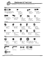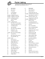
Page 7
BR 3070
Assembly Instructions
Hardware Required
Bolts
Washers
Nuts
[each 1 Piece]
Hardware Required
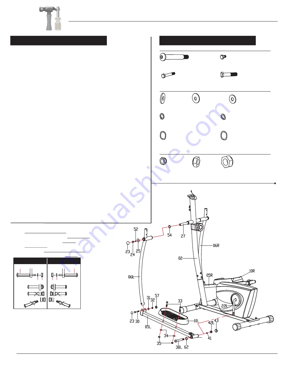
Please refer to the diagram below and pay special attention to corresponding
left & right side parts. Misplacing parts during assembly will lead to incorrect
assembly and may result in serious injury.
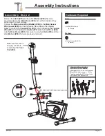
Pedal Hinge Bolt (#38L)
and CLOCKWISE to tighten
Left Nylon Nut (#42L)
with BLACK inner nylon ring.
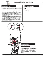
A s s e m b l y S t e p 3
A s s e m b l y S t e p 3
#38L/R. Left/Right Pedal Hinge Bolt
[each 1 Piece]
#30. Hex Bolt
(M8×55 mm)
[2 Pieces]
#33. Hex Bolt
(M10×45 mm)
[4 Pieces]
#24. Hex Bolt (M8×15 mm)
[2 Pieces]
#41. Spring Washer (Φ13×B2)
[2 Pieces]
#31. Washer
(M8,t1.5)
[2 Pieces]
#34. Washer (M10)
[4 Pieces]
#25. Washer
(M8, t2.0)
[2 Pieces]
#52. Spring Washer (M8)
[2 Pieces]
#62. Special Washer
(D17×0.3)
[2 Pieces]
#54. Special Washer
(Φ20)
[2 Pieces]
#32. Nylon Nut
(M8)
[2 Pieces]
#35. Nylon Nut
(M10)
[4 Pieces]
#42L. Left Nylon Nut
#42R. Right Nylon Nut
LEFT SIDE
RIGHT SIDE
38L
38R
41 42L 42R41
40L
Note:
Keep the
Left/Right Pedal Hinge Bolt
(#38L/38R)
perfectly
straight as they go
through the
Left/Right Pedal Connection
Joint (#40L/R)
and the
Crank (#22L/R).
If the
Left/Right Pedal Hinge Bolt (#38L/38R)
are connected to the
Crank (#22L/22R)
incorrectly,
damage to the
Left/Right Pedal Hinge Bolt
(#38L/38R)
and
Crank (#22L/22R)
will occur.
PLEASE NOTE:
b):Turn CLOCKWISE to tighten the
Right Pedal Hinge
Bolt (#38R)
and COUNTERCLOCKWISE to tighten
Right Nylon Nut (#42R)
with WHITE inner nylon ring.
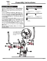
Remove two
Hex Bolts (#24)
, two
Spring Washers (#52)
, two
Washers (#25)
and two
Special Washers (#54)
that are
pre-assembled on the
Front Post Axle (#27)
and set them aside
as they will be used in a later process.
Insert the
Front Post Axle (#27)
through the
Front Post (#02).
Make sure the
Front Post Axle (#27)
is centered. If you encounter
too much friction, try using WD40 or Vaseline asa lubricant.
Slide one
Special Washer (#54)
onto the left side of the
Front Post
Axle (#27)
then followed by
Left Coupler Bar (#06L).
Secure them
together by hand tighten one
Hex Bolt (#24),
one
Spring Washer
(#52)
and one
Washer (#25)
that were previously removed.
Align and attach the left
Pedal Connection Joint (#40L)
on the
Left Pedal Arm (#05L)
to the left
Crank (#22L)
. Insert
Left Pedal
Hinge Bolt (#38L)
through a
Special Washer (#62)
followed by
left
Pedal Connection Joint (#40L)
and left
Crank (#22L)
. Screw
the
Left Pedal Hinge Bolt (#38L)
tightly into the left
Crank (#22L)
by turning COUNTERCLOCKWISE and then secure it by hand tighten
one
Spring
Washer
(#41)
and one
Left Nylon Nut (#42L)
by turning it
CLOCKWISE.
Align and attach the
Left Coupler Bar (#06L)
to the
Left Pedal
Arm (#05L)
. Hand Tighten them together using a
Hex Bolt (#30),
a
Washer (#31)
and a
Nylon Nut (#32).
At this point secure the
Hex Bolts (#24), Hex Bolt (#30)
and
Left
Nylon Nut (#42L)
that were hand tightened previously.
Attach
Bolt Cap (#23)
to the end of
Hex Bolt (#24)
and
Hex Bolt
(#30).
Attach
Bolt Cap (#43)
to the end of
Left Nylon Nut (#42L).
Attach
Bolt Cap (#57)
to the end of
Nylon Nut (#32).
Attach the
Left Pedal (#10L)
to the
Left Pedal Arm (#05L)
and
secure them together using two
Hex Bolts (#33),
two
Washers
(#34)
and two
Nylon Nuts (#35).
Repeat this process on the other side.
a):Turn COUNTERCLOCKWISE to tighten the
Left


