Assembly Instructions
Page 8
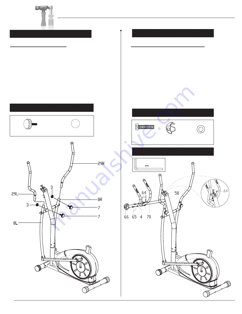
HANDLE BAR ASSEMBLY
Insert the two
Handle
B
ars
(#29
L & 29R
)
into the
openings at the end of the two
Coupler Bars
(#8L & #8R)
. Secure the
Handle
B
ars
(#29)
using two
Knob
B
olts
(#7)
. Place two
Bolt
C
aps (#3)
on the welded nuts located on the
opposite side of the
Knob
B
olts
(#7).
A s s e m b l y S t e p 4
Hardware Required
Hardware Required
A s s e m b l y S t e p 5
PULSE HANDLE BAR ASSEMBLY
Install the
Pulse
H
andle
B
ar (#70)
onto the
front side of the
Center
P
ost (#58)
using two
Bolts (#65)
and two
Spring
W
ashers (#4)
.
Feed the
Pulse
S
ensor
W
ire (#64)
through the
neck of the
Center
P
ost (#58)
until is sticking
out of the opening. You will need to connect
this wire to the
Computer (#51)
later. Slide
the
Clamp
C
over
(#66)
over the
Pulse
H
andle
B
ar
(#70)
.
Tool Required
#66. Clamp
C
over
[1 piece]
#65. Bolt
(M8x30 mm)
[2 pieces]
#4. Spring Washer
[2 pieces]
#7. Knob
B
olt
(M8x36 mm)
[2 pieces]
#3. Bolt Cap
[2 pieces]
Feed the Pulse
sensor wires (#64)
through the neck
of the Center post
(#58) until they are
sticking out of the
opening.
BRM3671/3681/3690


