background image

WARNING: SERIOUS INJURIES AND EVEN DEATH CAN OCCUR IF THE PROPER SAFETY PRECAUTIONS ARE NOT FOLLOWED. 

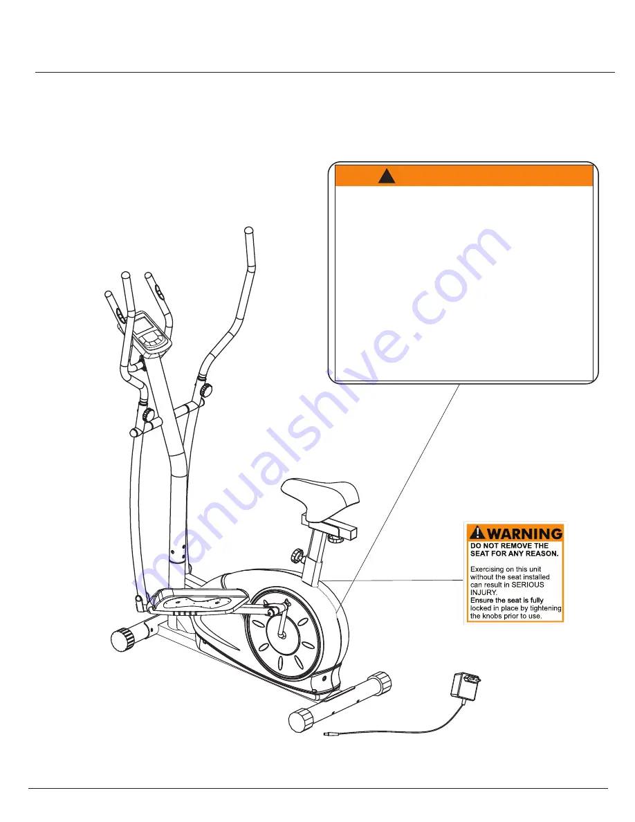
The diagram below highlights and reviews many of the important Safety and Warning labels also found

on the unit. Please ensure any user of the unit familiarizes themselves with these Safety and Warning

guidelines before use. 

PLEASE KEEP THESE INSTRUCTIONS FOR FUTURE USE & REFERENCE.

DO NOT DISCARD.

The use of this exercise equipment involves a 

RISK OF PHYSICAL INJURY

 as well as 

property damage, which can be minimized by observing the following guidelines: 

1. 

ALWAYS

 wear comfortable clothing 

and shoes with good traction. 

2. 

ALWAYS

 make sure all nuts and bolts 

are secured before use. TIGHTEN 

PEDAL HINGE BOLTS EVERY 30 

DAYS. 

3. 

STOP EXERCISING

 if you become 

dizzy, nauseous, have irregular 

heartbeats or breathing difficulties. 

Contact your physician immediately. 

4. 

ALWAYS

 keep a large mat under the 

Equipment to protect the floor or carpet. 

5. 

ALWAYS

 use your Equipment in a 

warm, dry, level well-lit and ventilated 

indoor area. 

7. 

ALWAYS

 keep your Equipment clean 

and free of dust, moisture, debris and 

loose objects. 

8. 

NEVER

 use the Equipment if you are 

injured or have a physical condition 

that impairs your balance. DO NOT 

exercise under the influence of 

medication or alcohol. 

9. 

NEVER

 allow small children or pets to 

approach the Equipment. It is not a 

toy. 

10. 

NEVER

 use the Equipment if you 

exceed its weight limit of 250 lbs. 

11. 

NEVER

 use the Equipment if it does 

not function properly. 

  6. 

 ALWAYS 

keep body and clothing free 

 and clear of all moving parts.

W A R N I N G !

!


Page 17

BRM3671/3681/3690

Summary of Contents for BRM /3690

Page 1: ...BRM 3671 3681 3690 OWNER S MANUAL This item is for consumer use only and it is not meant for commercial use For use under U S Patent numbers 6159132 D459773 D438264 ...

Page 2: ...This page intentionally left blank ...

Page 3: ...encing the assembly of your product or starting to exercise Please keep all children away from this item when in use Do not allow children to climb or play on them when they are not in use Supervise teenagers while they use this unit For your own safety always ensure that there is at least 3 feet of free space in all directions around your product while you are exercising Regularly check to see th...

Page 4: ...ight Pedal Bolt 2 pieces 27 Carriage Bolt M8x73 mm 4 pieces 38 Bolt M8x20 mm 4 pieces 4 Spring Washer for M8 bolt 4 pieces 5 Washer for M8 bolt 2 pieces 73 Washer for M8 bolt T1 5 mm 7 pieces 42 Washer for M10 bolt T2 0 mm 1 piece 47 Spring Washer for bolt 18 2 pieces 72 Nylon Nut for M 8 bolt 7 pieces 46 Nylon Nut for bolt 18 2 pieces 49 Cap Nut for M8 carriage bolt 4 pieces 7 Knob Bolt M8x36 mm ...

Page 5: ...ription 37 Arc Washer for M8 bolt 38 Bolt M8x20 mm 39 Spring Loaded Knob 41 U Bracket 42 Washer for M10 bolt 2 0 mm Thick 43 Knob M10 44 Seat Post Sleeve 45 Bolt Cap for bolt 18 46 Nylon Nut for bolt 18 47 Spring Washer for bolt 18 48 Main Frame 49 Cap Nut for M8 carriage bolt 51 Computer 54 Main Sensor Wire middle 58 Center Post 59 End Cap round 25 mm 60 Pulse Handle Bar Foam Grip 61 Pulse Sensor...

Page 6: ...ring the assembly process Please note that not all of the parts and hardware you see here will be used while you are assembling the machine because some of these items are already pre installed Please continue to the next page to begin the assembly process and use this page only as a reference guide for parts and hardware BRM3671 3681 3690 ...

Page 7: ...h it out 49 Cap Nut 4 pieces 27 Carriage Bolt M8x73 mm 4 pieces 37 Arc Washer 4 pieces REAR STABILIZER ASSEMBLY FRONT STABILIZER ASSEMBLY Secure the Front Stabilizer 69 to the Main Frame 48 using a total of two Carriage Bolts 27 two Arc Washers 37 and two Cap Nuts 49 Secure the Rear Stabilizer 26 to the Main Frame 48 using a total of two Carriage Bolts 27 two Arc Washers 37 and two Cap Nuts 49 BRM...

Page 8: ...he Center Post 58 onto the Main Frame 48 and secure it using a total of four Arc Washers 37 and four Bolts 38 A s s e m b l y S t e p 2 Hardware Required Tools Required 55 40 1 2 3 4 55 40 1 2 3 4 Make sure this wire is hanging out before assembling the Center post 58 38 Bolt M8x20 mm 4 pieces 37 Arc Washer 4 pieces Page 6 BRM3671 3681 3690 ...

Page 9: ... lower segment of the Coupler Bar 8L and align the Pedal Connection Joint 20 to the hole on the pedal crank Push the Left Pedal Bolt 18L through the hole on the pedal crank and secure it using one Spring Washer 47 the Nylon Nut 46 with black inner ring and then place a Bolt Cap 45 on top of the Nylon Nut 46 Repeat this process on the opposite side PLEASE NOTE a Turn COUNTERCLOCKWISE to tighten the...

Page 10: ...all the Pulse Handle Bar 70 onto the front side of the Center Post 58 using two Bolts 65 and two Spring Washers 4 Feed the Pulse Sensor Wire 64 through the neck of the Center Post 58 until is sticking out of the opening You will need to connect this wire to the Computer 51 later Slide the Clamp Cover 66 over the Pulse Handle Bar 70 Tool Required 66 Clamp Cover 1 piece 65 Bolt M8x30 mm 2 pieces 4 S...

Page 11: ...he Seat Post 36 by inserting the bolt on the bottom of theHorizontal Seat Bar 35 through the Seat Post 36 secure them using a adjust the distance of the seat from the Washer 42 and a Knob 43 This knob can be loosened to handle bars Make sure to tighten the knob after making any adjustment Attach the Insert the Seat Post 36 into the mouth of the post that is protruding from the Main Frame 48 down a...

Page 12: ... during step number 3 Troubleshooting BRM3671 3681 3690 COMPUTER ASSEMBLY Remove the Screws 63 that are pre assembled on the Computer 51 and set them aside for now Connect the Main Sensor Wire Middle 54 to the Main Sensor Wire Upper 52 Then connect the Pulse Sensor Wire Lower 64 to the Pulse Sensor Wire Upper 53 Attach the Computer 51 to the bracket on the Center Post 58 by using the four Screws 6...

Page 13: ...er moving parts which can gain great momentum during riding to come to a complete stop before dismounting the unit to avoid serious injury Do not use solvent cleaners If you are in any doubt do not use your cleansing product contact CUSTOMER SUPPORT SAFETY WARNINGS M a i n t e n a n c e C a r e For any replacement warning labels please contact our CUSTOMER SUPPORT at 888 266 6789 or 909 598 9876 o...

Page 14: ...p on the upper line press MODE to confirm b1 b1 M M M M b2 b3 b4 B 1 You may press ST STOP button to start training directly b2 or you may press UP DOWN buttons to adjust resistance level b3 During adjustment you will see the display changes when you press UP or DOWN buttons twice You may also adjust training resistance during training B 2 After adjustment of the training resistance you may press ...

Page 15: ...ved to zero will start from previous set data counting down and other set function data will keep counting up or down from previous records C 7 During all training period you may press ST STOP to stop monitor counting at anytime D Training in USER mode press UP button until USER shows up on the upper line press MODE to confirm d1 In USER mode you can set your own desired training program d1 d2 d3 ...

Page 16: ...ance will be adjusted automatically depends on your current heart beat If your heart beat is very high compare to the preset target the training resistance will decrease immediately one level and keep decreasing one level every 15 seconds by monitoring your current heart beat change If the training resistance has dropped to level one but your heart beat is still high the monitor will stop all func...

Page 17: ...our current heart rate reaches the preset target To select Target Heart Rate training mode for training please refer to the above Training in Target Heart Rate mode To ensure the heart rate readout is stable please hold the handgrip sensors with both hands during training RECOVERY After exercising for a period of time keep holding on handgrips and press RECOVERY button All function display will st...

Page 18: ...ll computer sensor wires are properly connected and are not damaged You may need to refer to installation assembly directions for the sensor wires in this manual If the computer display is blank not displaying any data or does not appear to power on please adjust the following 1 Check to ensure all sensor wires are all properly connected and are not damaged 2 Check to ensure the AC Adapter or Batt...

Page 19: ...EDAL HINGE BOLTS EVERY 30 DAYS 3 STOP EXERCISING if you become dizzy nauseous have irregular heartbeats or breathing difficulties Contact your physician immediately 4 ALWAYS keep a large mat under the Equipment to protect the floor or carpet 5 ALWAYS use your Equipment in a warm dry level well lit and ventilated indoor area 7 ALWAYS keep your Equipment clean and free of dust moisture debris and lo...

Page 20: ...Proof of purchase version 11 21 2013 BRM3671 3681 3690 MADE IN CHINA Model Number BRM 3671 3681 3690 ...

Reviews: