background image

Safety and Maintenance

•  Make sure all nuts, bolts, and screws are tightened prior to use.

•  Be sure that all adjustment locking devices and safety devices are properly engaged prior to use!

•  Never over-tighten the above-mentioned devices and parts to avoid damage to the unit.

•  Check for loose parts and components and make proper adjustments prior to use.

•  Check to see if there are any tears or bends in the welding or metal prior to use. If tears or bends are found,  

DO NOT use the unit and contact our CUSTOMER SUPPORT.

• 

Extreme care must be taken to not allow your feet, fingers, hair, clothing, and/or any loose items to be snagged into 

any portion of the bike when the unit is in motion. Failure to follow these instructions could result in serious injury, 

including the loss of fingers.

•  Always wait for the pedals and other moving parts (which can gain great momentum during riding) to come to a  

complete stop before dismounting the unit to avoid serious injury.

NOTE:

 Always wait for the pedals and/or any other moving parts (which can gain great momentum during riding)

to come to a complete stop before dismounting the unit to avoid serious injury.

•  To reduce speed on the bike, you may use the combinations of your feet on the Left/Right Pedals 

(#44/45)

 and your 

hands on the Left/Right Handlebars 

(#04L/#04R)

 to gently and safely apply counter-momentum.

•  Wait for the pedals to come to a complete stop.

•  Now you may safely dismount the unit

NOTE:


To safely move, transport, and/or store the unit, please seek the help of capable assistants (minimum of 2 people).  

The unit has integrated Front Rollers purposely intended to help ease this process.

•  Position one person on each side at the front of the bike toward the handle Bar  

(one person on the left, and one on the right).

•  Have each person use both hands to grip the corresponding Pulse Handle Bar 

(#05)

(These are the safest areas to avoid injury during this process.)

•  Have both people simultaneously lift the rear end of the unit, leaving the weight and pressure into the front of the unit 

and onto the Front Rollers to move/transport the unit to the desired area.

•  Please review all safety instructions and warnings in this entire Owner’s Manual, as well as any safety/warning labels 

affixed to the product before use.

•  Do not use solvent cleaners. If you are in any doubt, do not use your cleansing product; contact  

CUSTOMER SUPPORT.

• 

The specific parts on your unit which may see possible signs of wear after prolonged use are listed as follows 


(please check these parts before each use):  

Left/Right Pedals 

(#44/45)

; Left/Right Handlebars 

(#04L/#04R)

•  For any replacement warning labels, please contact our CUSTOMER SUPPORT at 


1 (888) 266-6789

 or 

1 (909) 598-9876

,  or mail in a written request to: 


Hupa International, Inc. 

21717 Ferrero Parkway 

Walnut, CA 91789 


More detailed information about how to reach our CUSTOMER SUPPORT may be found on Page 2 of the  

Owner’s Manual under the “CUSTOMER SUPPORT” section.

Safety & Warning

How To (Emergency) Stop

How To Move/Transport  The Bike For 

Maintenance & Care

BRM3635/BRM3810

Page  17

Summary of Contents for BRM3635

Page 1: ...BRM3635 BRM3810 DUAL TRAINER OWNER S MANUAL This product is intended for indoor home use only and is not to be used in a commercial setting ...

Page 2: ...This page is left blank intentionally ...

Page 3: ...ATH CAN OCCUR IF THE PROPER SAFETY PRECAUTIONS ARE NOT FOLLOWED The diagram below highlights and reviews many of the important Safety and Warning labels also found on the unit Please ensure any user of the unit familiarizes themselves with this Safety and Warning guidelines before use BRM3635 BRM3810 Page 1 ...

Page 4: ...on of the equipment and to warn them of the potential hazards If at any time during exercise you feel faint dizzy or experience pain stop and consult your physician Your product is intended for use in clean dry conditions You should avoid storage in excessively cold or damp places as this may lead to corrosion and other related problems If you have any questions concerning the assembly of your ite...

Page 5: ...ating noises and will cause damage to the equipment 1 It is only necessary to tighten the bolts and nuts to finger tight during the assembly process This will make it easier to complete certain steps by allowing more tolerance for all the parts to fit properly 2 Do not tighten all the nuts onto the bolts securely until after you have completed assembly of your product 3 Use wrenches pliers or ratc...

Page 6: ...eces Pre assembled 4 pieces 33 Washer M10 2 pieces 30 Spring Washer 1 2 2 pieces 34 Washer M8xφ26 mm 2 pieces Pre assembled 51 Washer M8 3 pieces Pre assembled 32 Wavy Washer 1 2 2 pieces 37 Wavy Washer φ19 mm 2 pieces Pre assembled 36 Arc Washer M8 8 pieces Pre assembled 4 pieces 31 Big Washer 2 pieces Pre assembled Hardware and Tool List Bolts Washers The following hardware is used to assemble y...

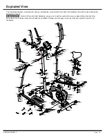
Page 7: ... Pre assembled 39 Nylon Nut M10 2 pieces 42 Nut M8 4 pieces 40 Left Nylon Nut with black inner nylon ring 1 2 1 piece 41 Right Nylon Nut with white inner nylon ring 1 2 1 piece Hardware and Tool List Others Nuts Tools Included The following hardware is used to assemble your unit Please take a moment to familiarize yourself with these items PLEASE NOTE Most of these parts are already pre assembled ...

Page 8: ...er 09 followed by the rear of the Main Frame 01 then secure them together using two Arc Washers 36 and two Nuts 42 Note Front Stabilizer 08 has end caps that spin for ease of relocating the unit and the Rear Stabilizer 09 has height adjustable end caps for leveling of the unit A FRONT STABILIZER ASSEMBLY Hardware Required Front Roller Height Adjustable End Caps Make sure these two wires are access...

Page 9: ...e it using the four Bolts 16 four Spring Washers 29 and four Arc Washers 36 B SEAT POST ASSEMBLY Insert the Seat Post 47 into the mouth of the post that is protruding from the Main Frame 01 down a minimum of 4 inches to engage the lowest hole Make sure the holes on the Seat Post 47 are facing the front before inserting Secure the Seat Post 47 using the Spring Loaded Knob 49 Hardware Required 11 12...

Page 10: ...al Tube 03R then the lower bracket of the Pedal Connection Joint 06R Secure them with a Washer 35 and a Nylon Nut 38 Repeat this process on the other side using the Left Pedal Connection Joint 06L Attach four Bolt Caps 27 on two Hex Bolts 27 as illustrated in the drawing 20 Hex Bolt M8x45 mm 2 pieces 35 Washer M8xφ16 mm 2 pieces 38 Nylon Nut M8 2 pieces 27 Bolt Cap S14 4 pieces BRM3635 BRM3810 Pag...

Page 11: ...dal Tube 03L onto the Crank 10 as illustrated and secure by inserting from the outer edge of the Left Pedal Tube 03L one Pedal Hinge Bolt 18L and one Wavy Washer 32 Secure from the inner side behind the Crank 10 with one Spring Washer 30 and one Left Nylon Nut 40 Secure the 18L by turning it COUNTER CLOCKWISE Repeat this process on the other side using the Right Pedal Tube 03R Secure the 18R by tu...

Page 12: ... and Nylon Nuts 52 that are pre assembled on the back of the Seat 50 and set them aside as they will be used later in this step Attach the Seat 50 to the Horizontal Seat Bar 48 using a total of three Washers 51 and three Nylon Nuts 52 Insert the Horizontal Seat Bar 48 into the Seat Post 47 Insert a Knob Bolt 26 through a Washer 35 followed by the Seat Post 47 and Horizontal Seat Bar 48 secure them...

Page 13: ...er side using Right Handle Bar 07R and Right Coupler Bar 04R B PEDAL ASSEMBLY Attach one Left Pedal 44 as oriented below in diagram to the Left Pedal Tube 03L and secure them together using two Hex Bolts 22 Two Washers 35 and two Nylon Nuts 38 Repeat this process on the other side using Right Pedal 45 onto the Right Pedal Tube 03R 14 Carriage Bolt M8x27 mm 4 pieces 17 Bolt M6x15 mm 4 pieces 35 Was...

Page 14: ...46 to the bracket of the Center Post 02 using four Screws 25 Tension Adjustment To increase the tension higher level of intensity turn the Tension Controller 16 in a clockwise direction To decrease the tension lower level of intensity turn the Tension Controller 16 in a counter clockwise direction 1 is the lowest level of tension easiest level for workout 8 is the highest level of tension most dif...

Page 15: ...s of pulse measurement because of the contact jamming the measurement value may be higher than the virtual pulse rate during the first 2 3 seconds then will return to normal level The measurement value can not be regarded as the basis of medical treatment Press MODE button until PULSE appears Press SET button to set exercise pulse The setting values of 40 240 RPM the consumer computer alarm when h...

Page 16: ...tion to install or replace the batteries NOTE 1 Do not mix a new battery with an old battery 2 Use the same type of battery Do not mix an alkaline battery with another type of battery 3 Rechargeable batteries are not recommended 4 Battery disposal should be handled according to all state and federal laws and regulations 5 Do not dispose of batteries in fire BRM3635 BRM3810 Page 14 ...

Page 17: ... Bolt Cap S14 28 Bolt Cap S17 29 Spring Washer M8 30 Spring Washer 1 2 31 Big Washer 32 Wavy Washer 1 2 33 Washer M10 34 Washer M8xφ26 mm 35 Washer M8xφ16 mm 36 Arc Washer M8 37 Wavy Washer φ19 mm 38 Nylon Nut M8 Description 39 Nylon Nut M10 40 Left Nylon Nut with black inner nylon ring 1 2 41 Right Nylon Nut with white inner nylon ring 1 2 42 Nut M8 43 Plastic Washer 44 Left Pedal 45 Right Pedal ...

Page 18: ...are that will be used during the assembly process Not all of the parts and hardware you see here will be used while you are assembling the machine because some of these items are already pre installed Please use this page only as a reference guide for parts and hardware PLEASE NOTE BRM3635 BRM3810 Page 16 ...

Page 19: ...ount the unit NOTE To safely move transport and or store the unit please seek the help of capable assistants minimum of 2 people The unit has integrated Front Rollers purposely intended to help ease this process Position one person on each side at the front of the bike toward the handle Bar one person on the left and one on the right Have each person use both hands to grip the corresponding Pulse ...

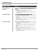
Page 20: ...roduct manual to determine if your model uses either AC Adapter or batteries to power your unit If the computer is not picking up your hand pulse signal or you are getting inaccurate readings please adjust the following 1 Slightly moisten dampen the palms with water so the sensors can detect a pulse signal 2 Do not grip the sensors too tightly Only moderate pressure need be applied 3 Gripping the ...

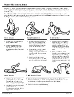
Page 21: ... you tuck your chin and arch your back upward 2 Return to the starting position slowly 1 Sit with your leg extended and bend your right knee as you cross your right leg over your left leg Your right foot of your extended leg foot should be flat on the floor alongside your left knee 2 Place your left arm on the outside of your right leg and pull against that leg while twisting your trunk as far as ...

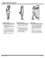
Page 22: ... left hand 2 Flex your right leg behind you grasp your ankle or foot with your right hand and pull your foot toward your buttocks Keep your back straight and right knee pointed down Repeat on the other leg 1 Place both hands against a wall to aid your balance Press the ball of your left foot against the wall and keep the heel of the same foot rested on the floor make sure your left knee is bent 2 ...

Page 23: ...This page is left blank intentionally ...

Page 24: ...ase Serial Number Date of Purchase Retailer Hupa International Inc 21717 Ferrero Parkway Walnut CA 91789 Phone 1 888 266 6789 Fax 1 909 598 6707 Email info hupa net Ver 09 19 2019 Printed in China THANK YOU FOR YOUR PURCHASE MODEL NO BRM3635 BRM3810 ...

Reviews: