background image

19

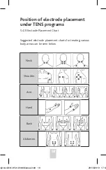
Neck

Shoulder

Arm

Hand

Back

Abdomen

Hip

Leg

Foot

Joint (knee)

Joint (elbow)

Joint (ankle)

Joint (wrist

Bodyclock3in1-85x140mmManual.indd   19

29/10/2019   17:12

Summary of Contents for 3-in-1 COMBO

Page 1: ...Instructions for use 3 in 1 COMBO E LECTROTH E RAPY odyclock3in1 85x140mmManual indd 1 29 10 2019 17 12 ...

Page 2: ...tion 13 5 Operating instructions 14 6 Instructions for use 21 7 Cleaning and maintenance 29 8 Troubleshooting 31 9 Storage 33 10 Disposal of device 33 11 Electromagnetic compatibility EMC tables 34 12 Explanation of symbols 40 13 Warranty 41 odyclock3in1 85x140mmManual indd 2 29 10 2019 17 12 ...

Page 3: ... Each program controls the generated electric impulses their intensity frequency and pulse width Please see page 42 for a summary of the programs available The unit works by passing mild electrical impulses through the skin via electrode pads into the nerve and muscle fibres which lie below The intensity of the unit can be adjusted independently and applied individually to one or more body parts T...

Page 4: ...us creating the perception of there being no pain Low frequency TENS currents facilitate the release of endorphins the body s natural painkillers 1 2 3 What is EMS EMS stands for Electronic Muscle Stimulation This treatment consists of delivering electrical impulses through the skin into the nerve fibres and muscles that lie beneath Skin contact is made via surface electrodes placed on the body Th...

Page 5: ...ary relief of pain associated with sore and aching muscles in the neck shoulder back joint hip hand abdomen foot upper extremities arm and lower extremities leg due to strain from exercise or normal household work activities 2 EMS mode The EMS stimulation program stimulates muscles in order to improve and facilitate muscle conditioning 3 Massage mode The Massage stimulation program provides muscle...

Page 6: ...ctronic devices Such use could cause electric shock burns electrical interference or death 2 Stimulation should not be applied over swollen infected inflamed areas or skin eruptions e g phlebitis thrombophlebitis varicose veins etc 3 Electrode placements must be avoided in the carotid sinus area front and side of neck or transcerebrally through the head 4 Do not use if you have a suspected or diag...

Page 7: ...ause rhythm disturbances to your heart which could be lethal 5 Do not apply stimulation over or in proximity to cancerous lesions 6 Do not apply stimulation in the presence of electronic monitoring equipment e g cardiac monitors ECG alarms which may not operate properly when the electrical stimulation device is in use 7 Do not apply stimulation when in the bath or shower 8 Do not apply stimulation...

Page 8: ...to cardiac arrest 15 Never use on the eyes head and face or genital areas 16 Never use on skin areas lacking normal sensation 17 Keep electrodes separated during treatment Improper stimulation or skin burns could result if electrodes are in contact with each other 18 Keep the stimulator out of reach of children 19 Consult your doctor or supervisory medical professional if you are in any doubt what...

Page 9: ... occurs please discontinue use 8 If you have a suspected or diagnosed heart disease or epilepsy you should follow precautions recommended by your physician 9 Caution if you have a tendency to bleed internally e g following an injury or fracture Seek medical advice before using this unit 10 Consult with your physician prior to the use of the device after a recent surgical procedure because stimulat...

Page 10: ...17 This device should only be used with electrodes recommended by Body Clock Health Care Ltd 2 2 4 Adverse Reactions 1 Possible skin irritation or electrode burns under the electrodes may occur If so discontinue use immediately 2 On very rare occasions first time users of TENS report feeling light headed or faint We recommend that you use the product while seated until you become accustomed to the...

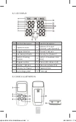
Page 11: ...ttery indicator 11 Intensity for Channel 2 4 Symbol of setting function 12 Symbol of treatment time min 5 Program number 13 Pulse width indicator uS 6 Channel 1 indicator 14 Pulse rate indicator Hz 7 Intensity for Channel 1 15 Treatment time 8 Key locking symbol 16 Timer sign 3 2 LCD DISPLAY 3 3 DEVICE ILLUSTRATION odyclock3in1 85x140mmManual indd 11 29 10 2019 17 12 ...

Page 12: ...ent time or to increase the pulse rate and pulse width in the user mode which is only relevant to the TENS and EMS treatment modes 5 CH2 button Press the CH2 button to increase the intensity of CH2 Press the CH2 button to increase the treatment time or to increase the pulse rate and pulse width in the user mode which is only relevant to the TENS and EMS treatment modes 6 CH2 button Press the CH2 b...

Page 13: ... 5 x 23mm L xW xT Weight Approx 70g without batteries Automatic Shut off 1 minute Classification BF type applied part internal power equipment IP22 Electrodes pads 50x50mm square Output precision 20 error is allowed for all the output parameters TENS MODE 9 PROGRAMS P W PulseWidth 100 300μs P R Pulse Rate 2 120Hz Hz vibration per second Treatment time 5 90 minutes EMS MODE 8 PROGRAMS P W PulseWidt...

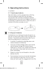
Page 14: ...cling of used batteries Household batteries should be taken to your nearest recycling centre or collection point 1 If a battery is swallowed accidentally please seek medical assistance immediately 2 In the case of battery leakage please avoid contact with the battery through skin eyes and mucus membranes If contact occurs please wash that body part with plenty of clean water and contact your docto...

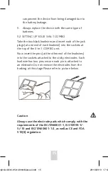
Page 15: ... COMBO unit Now insert the pins at the other end of the leadwires into the sockets attached to the sticky electrodes Each leadwire has two pins ensure each pin is attached to an electrode Do not remove the electrodes from the backing at this stage Please refer to picture below Caution Always use the electrode pads which comply with the requirements of the IEC EN60601 1 ISO10993 1 5 10 and IEC EN60...

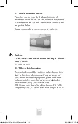
Page 16: ...e electrode wires into any AC power supply socket 5 3 ELECTRODES 5 3 1 Electrode information The electrodes should be routinely replaced when they start to lose their adhesiveness If you are unsure of your electrode adhesive properties please order new replacement electrodes For replacement electrodes please contact Body Clock Health Care 108 George Lane South Woodford London E18 1AD Telephone 44 ...

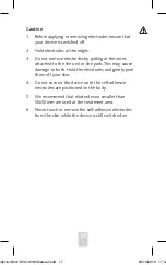
Page 17: ...s may cause damage to both Hold the electrodes and gently peel them off your skin 4 Do not turn on the device until the self adhesive electrodes are positioned on the body 5 We recommend that electrodes no smaller than 50x50mm are used at the treatment area 6 Never touch or remove the self adhesive electrodes from the skin while the device is still switched on odyclock3in1 85x140mmManual indd 17 2...

Page 18: ... Abdomen Position of electrode placement under TENS programs 5 4 3 Electrode Placement Chart Suggested electrode placement charts for treating various body areas can be seen below odyclock3in1 85x140mmManual indd 18 29 10 2019 17 12 ...

Page 19: ...19 Hip Leg Foot Joint knee Joint elbow Joint ankle Joint wrist odyclock3in1 85x140mmManual indd 19 29 10 2019 17 12 ...

Page 20: ...20 Neck Shoulder Arm Hand back Abdomen Hip foot Leg Position of electrode placement under EMS programs odyclock3in1 85x140mmManual indd 20 29 10 2019 17 12 ...

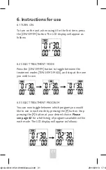
Page 21: ...ween the treatment modes TENS EMS MASS and stop at the one you wish to use 6 3 SELECT TREATMENT PROGRAM You can now toggle between which program you would like to use in each mode by pressing the P button Stop pressing the P button at your desired choice Please see page 42 for a full listing of programs available within each mode The LCD display will appear as follows odyclock3in1 85x140mmManual i...

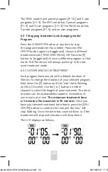
Page 22: ... starts flashing on the LCD screen Use the button on either channel to select the length of your treatment The timer function can be increased decreased in increments of one minute at a time The minimum treatment time is 5 minutes the maximum is 90 minutes Once you have your desired treatment time frame press the ON OFF M button to confirm the time and the min will stop flashing Once the timer has...

Page 23: ...to page 42 for an overview of the parameters used for each user program The LCD displays as opposite You will now see the Hz symbol flashing on the right You can adjust the pulse rate to your desired setting by using the buttons on either channel press the P button to set The LCD displays as opposite You will now see the μs symbol flashing you can adjust the pulse width to your desired setting by ...

Page 24: ...ncrease to a higher level after each press The device has 40 levels of output intensity Please adjust the intensity to the level that you feel comfortable The level of output intensity will be shown on the LCD You can set the length of the treatment by adjusting the minutes using the buttons on either channel When you are happy with the amount of time set press the ON OFF M button to confirm The L...

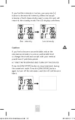
Page 25: ...e ON OFF M button to stop treatment during the treatment mode Press the ON OFF M button again to turn off the stimulator and the LCD will become blank If you feel the intensity is too low you can press button to decrease the intensity When the output intensity of both channels decrease to zero the unit will return to the standby mode The LCD displays as follows Low intensity Zero intensity odycloc...

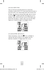
Page 26: ... the intensity is above level 4 If it hasn t detected the load or any electrode is not maintaining sufficient contact with the skin the intensity will automatically return to level 0 and the symbol will flash returning the unit to standby mode Switch off the unit and check that your electrodes are fully in contact with your skin and then begin your treatment again See diagram below odyclock3in1 85...

Page 27: ...es and the skin deteriorates over time f The adhesive force of the electrodes depends on the user s skin properties storage conditions and the number of applications If your electrode pads no longer fully stick to the skin s surface replace them with new ones Stick the electrode pads back onto the protective film after use and store them in the storage bag to prevent them from drying out This reta...

Page 28: ...ase of painful muscle groups attach the electrodes in such a way that the affected muscles are also surrounded by the electrodes Usage advice for TENS If you do not feel any discomfort during the treatment we advise you to use the device until the session ends We suggest 1 2 treatments per day while needed If you have any doubts please seek advice from your supervisory medical professional on trea...

Page 29: ...rt build up you may also apply a mild detergent 7 1 3 Store the unit in a cool dry place Do not hold the unit under running water nor submerge it in water or other liquids 7 1 4 The unit is sensitive to heat and should not be exposed to direct sunlight Do not place it on hot surfaces 7 1 5 Do not use any chemical cleaners or abrasive agents for cleaning 7 1 6 Ensure that no water penetrates into t...

Page 30: ... to open the device or attempt to make any modifications or repairs to the device or any of its accessories 7 2 3 Opening of the equipment by unauthorised persons is not permitted and will invalidate the warranty The product does not require calibration If your product does not reach the expected performance please contact the distributor odyclock3in1 85x140mmManual indd 30 29 10 2019 17 12 ...

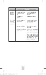
Page 31: ...correct type No sensation of stimulation 1 The electrode does not have sufficient connection to the skin 2 The electrode does not have sufficient connection to the stimulator 3 The battery is used up 4 The electrodes are dry 5 The treatment time has finished 1 Check that the electrodes are making full contact with the skin 2 Check the connection ensuring both leadwires and jack plug sockets are wo...

Page 32: ...rode has not stuck well to the skin 3 The skin is sensitive to the electrode 1 Do the treatment once a day and shorten the treatment time 2 Check and stick the electrode well or replace electrodes 3 Check your allergy history Please change the position of the electrode or shorten the treatment time If your skin is sensitive you may try on electrodes with sensitive gel If sensitivity persist stop t...

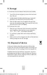
Page 33: ... box in a cool dry place 10 c 55 c 10 90 relative humidity 2 Do not keep in places that can be easily reached by children 3 When not in use for a long period remove the batteries before putting the unit into storage 10 Disposal of device At the end of the product life cycle do not throw this product into the normal household waste but bring it to a collection point for the recycling of electronic ...

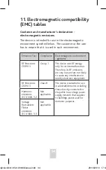
Page 34: ...he device uses RF energy only for its internal function Therefore its RF emissions are very low and are not likely to cause any interference in nearby electronic equipment RF Emissions CISPR11 Class B The device is suitable for use in all establishments including those directly connected to the public low voltage power supply network that supplies to buildings power used for domestic purposes Harm...

Page 35: ...e at least 30 Electrical fast transient burst IEC 61000 4 4 2 kV for power supply lines Not applicable Not applicable For INTERNALLY POWERED ME EQUIPMENT Surge IEC 61000 4 5 1 kV line s to line s Not applicable Not applicable For INTERNALLY POWERED ME EQUIPMENT Guidance and manufacturer s declaration electromagnetic immunity The device is intended for use in the electromagnetic environment specifi...

Page 36: ...s 70 UT 30 dip in UT for 25 cycles 5 UT 95 dip in UT for 5 sec Not applicable not applicable For INTERNALLY POWERED ME EQUIPMENT Power frequency 50Hz 60Hz magnetic field IEC 61000 4 8 10V m 10V m Power frequency magnetic fields should be at levels characteristic of a typical location in typical commercial or hospital environment NOTE UT is the a c mains voltage prior to application of the test lev...

Page 37: ...s the maximum output power rating of the transmitter in watts W according to the transmitter manufacturer and d is the recommended separation distance in metres m Field strengths from fixed RF transmitters as determined by an electromagnetic site surveya should be less than the compliance level in each frequency rangeb Interference may occur in the vicinity of equipment marked with the following s...

Page 38: ...mitters an electromagnetic site survey should be considered If the measured field strength in the location in which the device is used exceeds the applicable RF compliance level above the device should be observed to verify normal operation If abnormal performance is observed additional measures may be necessary such as reorienting or relocating the device b Over the frequency range 150 kHz to 80 ...

Page 39: ...0 LTE Band 7 Pulse modu lation b 217Hz 2 0 3 28 5240 5100 5800 WLAN 802 11 a n Pulse modu lation b 217Hz 0 2 0 3 9 5500 5785 NOTE If it is necessary to achieve the IMMUNITY TEST LEVEL the distance between the transmitting antenna and the ME EQUIPMENT or ME SYSTEM may be reduced to 1m The 1m test distance is permitted by IEC 61000 4 3 a For some services only the uplink frequencies are included b T...

Page 40: ...o instruction manual The first number 2 Protects against solid foreign objects of 12 5mm Ø and greater The second number Protects against vertically falling water drops when enclosure up to 15º Vertically falling drops shall have no harmful effects when the enclosure is at any angle up to 15º on either side of the vertical Found on the label at the back of the unit Manufacturer information The man...

Page 41: ...COMBO unit is guaranteed for a period of 1 year against manufacturer s defects The guarantee does not include leads electrodes or batteries Applies to purchases only Guarantee odyclock3in1 85x140mmManual indd 41 29 10 2019 17 12 ...

Page 42: ...Adjustable 2 100 Default 160 260 Adjustable 100 300 55 U3 Default 260 Adjustable 100 300 46 EMS P01 Default 30 Adjustable 5 90 4 200 60 P02 20 57 P03 50 57 P04 60 51 P05 50 57 U1 Default 5 Adjustable 2 100 Default 300 Adjustable 100 300 48 U2 Default 60 Adjustable 20 100 Default 200 Adjustable 100 300 51 U3 Default 70 Adjustable 20 100 Default 200 Adjustable 100 300 46 MASSAGE P01 30 8 300 61 P02 ...

Page 43: ...43 odyclock3in1 85x140mmManual indd 43 29 10 2019 17 12 ...

Page 44: ...5 Shenzhen Roundwhale Technology Co Ltd Add 202 2 F Building 27 Dafa Industrial Park Longxi Community Longgang Street Longgang District Shenzhen China EU Representative Shanghai International Holding Corp GmbH Europe Eiffestrasse 80 20537 Hamburg Germany This manual is recyclable 2460 odyclock3in1 85x140mmManual indd 44 29 10 2019 17 12 ...

Reviews: