background image

Body Clock Stimplus Pro

Instructions for use

TM

BodyclockStimplusProManual2016.qx8_Layout 1  10/08/2016  10:23  Page 1

Summary of Contents for Stimplus Pro

Page 1: ...Body Clock Stimplus Pro Instructions for use TM ...

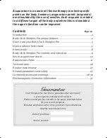
Page 2: ...s Information 31 Acupuncture is an ancient Chinese therapy in which specific points on the body known as acupuncture points acupoints are stimulated by the use of needles Each acupoint is related to a different organ of the body and when this is stimulated the organ s function can be improved Guarantee Your Stimplus Pro machine is guaranteed for a period of 2 years against manufacturer s defects P...

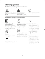
Page 3: ...U only This symbol indicates the serial number of the device and includes the month and year of manufacture and can be found on the back of the unit The first number 2 Protected against access to hazardous parts with a finger and the jointed test finger of 12 mmФ 80 mm length shall have adequate clearance from hazardous parts and protected against solid foreign objects of 12 5 mmФ and greater The ...

Page 4: ... for personal or professional use Unique Features Audio and visual LED acupoint detection indicators Audio and visual LED intensity indicator Intensity levels indicated by 6 LEDs 3 choices of stimulation rhythm Optional timer to select treatment duration Stimulation of acupoints with micro current therapy Differential amplifier Safe to use Precise micro computer controlled Ergonomic design Compact...

Page 5: ...d it drops again if you move the tip away from the point You will know you have located a point when the pitch is at its highest Visually the proximity of an acupoint is indicated by the number of LEDs which are alight When three or more LEDs are alight the tip is very close to a point If all the LEDs are lit up the tip is over a point 4 Please Note If the skin is very dry we recommend you use a m...

Page 6: ...ns the beeping sound stops and the green light on the top of the unit flashes indicating stimulation Using the intensity control you can adjust the intensity to a comfortable level by pressing either or to increase or decrease intensity The intensity level is also indicated by the LED scale If the LED nearest to the tip is flashing the intensity is set at minimum If the LED flashing is furthest fr...

Page 7: ...g your Body Clock Stimplus Pro do not forget to turn it off How to achieve best results from your Body Clock Stimplus Pro To ensure proper operation and to achieve best results please read the following information for guidance 1 When holding the unit physical contact must be made between the passive contact plate and the web of your hand 2 The Body Clock Stimplus Pro should be held by the person ...

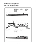
Page 8: ...son to treat another without having to make physical contact with their skin The wrist strap consists of a lead with a bracelet attachment at one end and a jack plug at the other When the wrist strap is to be used the jack plug should be inserted into the jack socket on the underside of the device see diagram on page 9 The bracelet section should be worn by the patient 5 A precision extension tip ...

Page 9: ... before using the Body Clock Stimplus Pro by a thoroughly washing the skin sites to be treated with a mild soap and water solution to remove any non conductive skin oils b rinsing the area with warm water and drying thoroughly Electrode Placement Gold Tip see page 6 For pain reduction place the gold tip on or above the point of pain 7 ...

Page 10: ... stimulation time the detection beeper sound is replaced by a green flashing light which indicates stimulation is taking place Three LED flashing light frequencies correspond to the three stimulation frequencies rhythms selected by the user Once stimulation is over the device returns automatically to search mode The stimulation signal from the Body Clock Stimplus Pro has a unique waveform which ha...

Page 11: ...ntensity Indicator Low Battery Indicator 2 5mm Earphone Jack Stim Switch Intensity Switch Rhythm Switch Tip gold plate Passive Contact Plate Passive Electrode Time Selector Switch Jack Socket Return Path Battery Compartment Power Switch Body Clock Stimplus Pro controls and indicators ...

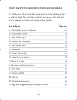
Page 12: ...ondary and supporting points Area of pain Page no A Pain in the arms or elbows 11 B Pain in the hands 12 C Pain in the legs 13 D Pain in the shoulder 14 E Pain in the neck 15 F Toothache 16 G Lower back pain 17 H Headache migraine 18 I Menstrual pain 19 J Nausea motion sickness 20 K Insomnia 21 L Sexual vitality 22 M Stress 23 N Smoking severance 24 O Appetite suppression for weight control 25 ...

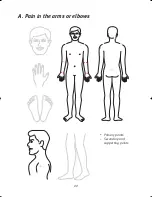
Page 13: ...11 A Pain in the arms or elbows Primary points Secondary and supporting points ...

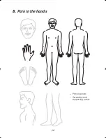
Page 14: ...12 B Pain in the hands Primary points Secondary and supporting points ...

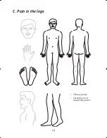
Page 15: ...13 C Pain in the legs Primary points Secondary and supporting points ...

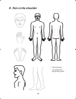
Page 16: ...14 D Pain in the shoulder Primary points Secondary and supporting points ...

Page 17: ...15 E Pain in the neck Primary points Secondary and supporting points ...

Page 18: ...16 F Toothache Primary points Secondary and supporting points ...

Page 19: ...17 G Lower back pain Primary points Secondary and supporting points ...

Page 20: ...18 H Headache migraine Primary points Secondary and supporting points ...

Page 21: ...19 I Menstrual pain Primary points Secondary and supporting points ...

Page 22: ...20 J Nausea motion sickness Primary points Secondary and supporting points ...

Page 23: ...21 K Insomnia Primary points Secondary and supporting points ...

Page 24: ...22 L Sexual vitality Primary points Secondary and supporting points ...

Page 25: ...23 M Stress Primary points Secondary and supporting points ...

Page 26: ...24 N Smoking severance Primary points Secondary and supporting points ...

Page 27: ...25 O Appetite suppression for weight control Primary points Secondary and supporting points ...

Page 28: ...m batteries included Classification BF Isolated Applied Part Transportation Storage temperature range 5 c 65 c Transportation Storage temperature humidity Up to 80 Product Life 2 years The radio shielding of the device has been ascertained according to VFG 243 1991 interference suppression of ISM devices Shapes of output curves under a 500 ohm common resistor carbon metal film resistor load Note I...

Page 29: ... the cover back using the corrugation Insert 2 x CR2034 lithium batteries The sides must be facing the back of the unit We also recommend that you remove the batteries during transportation When not in use store the device in its original packaging General precautions and safety 1 The Body Clock Stimplus Pro is CE marked and complies with EU and FDA Medical Device Regulations electrical and EMC sa...

Page 30: ... personnel The Body Clock Stimplus Pro is guaranteed for 2 years against manufacturer s defects NOTE The guarantee is null and void if any attempt is made to open the unit by unauthorised personnel In the event of a fault please contact the supplier details found on the invoice or delivery note Contraindications The Body Clock Stimplus Pro should not be used in conjunction with either a sensing or...

Page 31: ...hanism Keep this device out of the reach of children Electronic monitoring equipment such as ECG monitors and alarms may not operate properly when TENS is in use Portable and mobile RF communications equipment can affect medical electrical equipment Operation of the equipment or system below this amplitude or value may cause inaccurate results Check with your medical adviser before using this prod...

Page 32: ... Do not stimulate any area of skin which is sore or inflamed or does not have normal sensation 3 The Body Clock Stimplus Pro must be used in accordance with the EMC information posted in this manual 4 Portable and mobile RF communications equipment can affect the Body Clock Stimplus Pro 5 Simultaneous connection of a patient to high frequency surgical equipment could result in burns at the site of...

Page 33: ... below according to the maximum output power of the communications equipment Rated maximum Separation distance according to frequency of transmitter m output power of transmitter W 150kHz to 80MHz 80MHz to 800MHz 800MHz to 2 5GHz 0 01 0 12 0 12 0 23 0 1 0 38 0 38 0 73 1 1 2 1 2 2 3 10 3 8 3 8 7 3 100 12 12 23 For transmitters rated at a maximum power output not listed above the recommended separat...

Page 34: ...ld be less than the compliance level in each frequency range Interference may occur in the vicinity of equipment marked with the following symbol Note 1 At 80MHz and 800MHz the higher frequency applies Note 2 These guidelines may not apply in all situations Electromagnetic propagation is affected by absorption and reflection from structures objects and people a Field strengths from fixed transmitt...

Page 35: ... supply input lines IEC 61000 4 11 Power frequency 50 60Hz magnetic field IEC 61000 4 8 NOTE UT is the a c mains voltage prior to application of the test level Electromagnetic environmental guidance Floor should be wood concrete or ceramic tile If floors are covered with synthetic material the relative humidity should be at least 30 n a n a Power frequency magnetic fields should be at levels chara...

Page 36: ...ealth Care Ltd 108 George Lane South Woodford London E18 1AD United Kingdom Tel 44 0 20 8532 9595 Fax 44 0 20 8532 9551 www bodyclock net e mail customercare bodyclock net 0120 July 2016 2 This manual is recyclable ...

Reviews: