Assembly Instructions
Page 8
BRT 3980/3880
A s s e m b l y S t e p 3
#21. Pedal Hinge Bolt (φ16x1/2"x97 mm)
[2 Pieces]
#22. Screw
˄
M10x58 mm) [2 Pieces]
#30. Screw (M8x20 mm) [2 Pieces]
#38. Washer (M10)
[2 Pieces]
#40. Washer (M8)
[2 Pieces]
#42. D Shape Washer
(19 mm)
[2 Pieces]
#43. Special Washer
(ID19 mm)
[2 PIeces]
#44. Special Washer
(ID16 mm)
[2 Pieces]
#35. Nylon Nut (1/2")
[2 Pieces]
#36. Nylon Nut (M10)
[2 Pieces]
#61. Axle Cover [2 Pieces]
Others
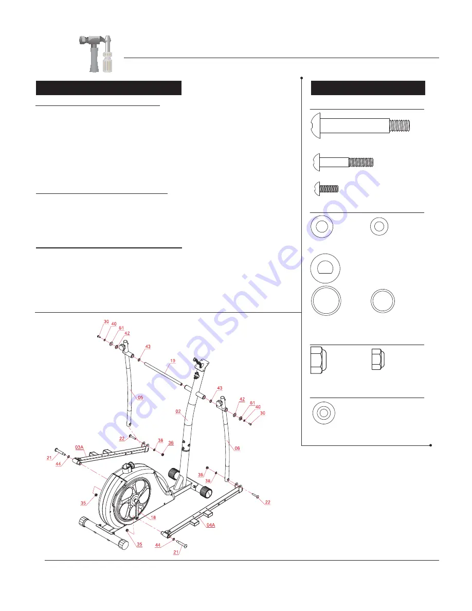
COUPLER BAR ASSEMBLY (Part I)
Referring to the diagram below, insert the
Axle (#19)
through the horizontal
stems on the
Center Post (#02)
. Then, on the left side of the
Axle (#19)
–in
the following order--slide on one
Special Washer (#43)
followed by the
Left
Coupler Bar (#05)
, one
D Shape Washer (#42)
, one
Axle Cover (#61)
,
one
Washer (#40)
, and secure using one
Screw (#30)
.
On the opposite side of the
Axle (#19)
, assemble –in the following order—
one
Special Washer (#43)
followed by the
Right Coupler Bar (#06)
, one
D Shape Washer (#42)
, one
Axle Cover (#61)
, one
Washer (#40)
, and
secure using one
Screw (#30)
.
COUPLER BAR ASSEMBLY (PART II)
Attach the
Right Pedal Tube (#04A)
onto the
Crank (#18)
as illustrated and
secure by inserting from the outer edge of the
Right Pedal Tube (#04A)
: one
Pedal Hinge Bolt (#21)
and one
Special Washer (#44)
. Secure from the
inner edge (behind the
Crank (#18)
) with one
Nylon Nut (#35)
.
Repeat this process on the other side using the
Left Pedal Tube (#03A)
.
Hardware Required
NUTS
WASHERS
BOLTS
COUPLER BAR ASSEMBLY (PART III)
Using the drawings as reference, attach the free end of the bottom of the
Right Coupler Bar (#06)
to the front of the
Right Pedal Tube (#04A)
by
aligning the holes. After the holes are aligned, insert one
Screw (#22)
through the
Right Pedal Tube (#04A)
,the
Right Coupler Bar (#06)
and
secure using one
Washer (#38)
followed by one
Nylon Nut (#36).
Repeat this process on the other side using
Left Coupler Bar(#05)
and
Left
Pedal Tube (#03A)
.


