background image

    Page 10

PT728/PT730

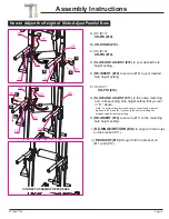
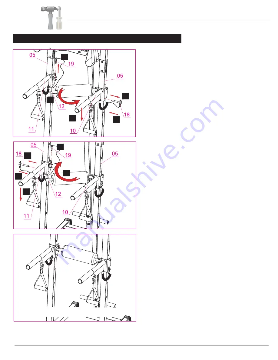
How to Adjust the Height of Slide-Adjust Parallel Bars

Assembly Instructions

      A.) 

On (#11):

UN-PIN (#19).

      C.) 

On (#10):

UN-PIN (#18). 

      B.) 

UN-HINGE (#12).

      D.) 

SLIDE AND ADJUST (#10) 

to your desired hole 

           height setting.

      E.) 

RE-INSERT (#18) 

to secure (#10) to your desired

           hole height setting

  H.) 

RE-INSERT (#18) 

to secure (#11) to the matching

       hole height setting.

  I.) 

RE-HINGE/RETURN (#12)

 to align with the holes 

      on the bracket (#11).

   J.)

 RE-INSERT (#19) 

through both the bracket on 

      (#11) and (#12).

 Note: To avoid serious injury and ensure correct usage, always

make sure (#10) and (#11) are set to the same matching and 

corresponding hole height setting. 

H

CORRECT ASSEMBLY REFERENCE

 F.) 

On (#11):


UN-PIN (#18).


 G.) 

SLIDE AND ADJUST (#11) 

to the same matching 

       and corresponding hole height setting that you set 

       in “D.” above.


A

B

C

D

E

F

G

I

J

Summary of Contents for PT728

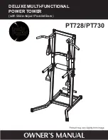
Page 1: ...DELUXE MULTI FUNCTIONAL POWER TOWER with Slide Adjust Parallel Bars PT728 PT730 ...

Page 2: ...se carefully and with caution you use this product at your own risk Perform your exercises at a moderate pace never perform jerky or uncoordinated movement that may cause injury It is recommended that you should work out with a partner 4 Do not allow children or minors to play on or around this equipment Teenagers using strength equipment should be supervised by an adult 5 Read and understand all ...

Page 3: ...ing the assembly of your product or starting to exercise Please keep all children away from this item when in use Do not allow children to climb or play on them when they are not in use Supervise teenagers while they use this unit For your own safety always ensure that there is at least 3 feet of free space in all directions around your product while you are exercising Regularly check to see that ...

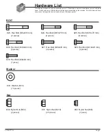
Page 4: ... you see parts on this page that are not included in your hardware packet 33 Washer M10 10 pieces Nut BOLT 23 Hex Bolt M12x85 mm 2 pieces 24 Hex Bolt M10x75 mm 4 pieces 25 Hex Bolt M10x70 mm 6 pieces Washer Page 3 PT728 PT730 26 Hex Bolt M10x60 mm 6 pieces 27 Hex Bolt M10x45 mm 4 pieces 28 Hex Bolt M10x25 mm 2 pieces 29 Hex Bolt M8x40 mm 1 piece 30 Nylon Nut M12 2 pieces 31 Nylon Nut M10 20 pieces...

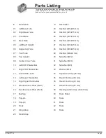
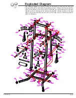
Page 5: ... Hex Bolt M10x45 mm 06 Supporting Tube 28 Hex Bolt M10x25 mm 07 Foot Tube 29 Hex Bolt M8x40 mm 08 Top Upright 30 Nylon Nut M12 09 Center Cross Tube 31 Nylon Nut M10 10 Left VKR Parallel Bar 32 Nylon Nut M8 11 Right VKR Parallel Bar 33 Washer M10 12 Foam Roller Tube 34 Square End Cap 50 mm 13 Left Upper Handle Bar 35 Round End Cap 38 mm 14 Right Upper Handle Bar 36 Round End Cap 32 mm 15 Reinforcem...

Page 6: ... the assembly process Please note that not all of the parts and hardware you see here will be used while you are assembling the machine because some of these items are already pre installed Please continue to the next page to begin the assembly process and use this page only as a reference guide for parts and hardware Page 5 PT728 PT730 ...

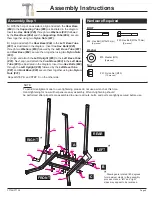
Page 7: ...Hardware Required A A With the help of an assistant align and attach the Rear Base 04 to the Supporting Tube 06 as illustrated in the diagram Insert two Hex Bolts 25 through two Washers 33 followed by the Rear Base 04 and the Supporting Tube 06 secure them together using two Nylon Nuts 31 33 Washer M10 6 pieces Nut BOLT 24 Hex Bolt M10x75 mm 4 pieces 25 Hex Bolt M10x70 mm 6 pieces Washer 31 Nylon ...

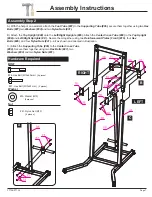
Page 8: ...the Center Cross Tube 09 to the Top Upright 08 and Left Right Uprights 0 Secure them together using two Reinforcement Plates Front 16 four Hex Bolts 26 and four Nylon Nuts 31 all as shown and oriented in illustration C Attach the Supporting Tube 06 to the Center Cross Tube 09 Secure them together using two Hex Bolts 27 two Washers 33 and two Nylon Nuts 31 A Hardware Required 33 Washer M10 4 pieces...

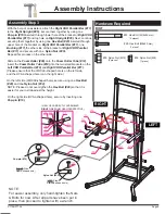
Page 9: ...d Right VKR Parallel Bar 11 Please ensure that the CIRCLE shaped hole is on the left side and the OVAL shaped hole is on the right side On the left side CIRCLE shaped hole secure using one Hex Bolt 29 and one Nylon Nut 32 NOTE Please do not over tigthen the Hex Bolt 29 so that it is easier for you to slide adjust the height On the right side OVAL shaped hole secure by inserting one Pop pin 19 PT72...

Page 10: ... 26 and one Nylon Nut 31 Attach the Sling Strap 21 to the Left Upper Handle Bar 13 with a Hook 20 Repeat this process on the opposite side Attach the Hand Strap 22 to the Left VKR Handle Bar 10 with a Hook 20 LEFT RIGHT The assembly process is now complete However for your own safety please make sure to read this entire Owner s Manual which includes safety instructions and warnings as well as any ...

Page 11: ...8 to secure 11 to the matching hole height setting I RE HINGE RETURN 12 to align with the holes on the bracket 11 J RE INSERT 19 through both the bracket on 11 and 12 Note To avoid serious injury and ensure correct usage always make sure 10 and 11 are set to the same matching and corresponding hole height setting H CORRECT ASSEMBLY REFERENCE F On 11 UN PIN 18 G SLIDE AND ADJUST 11 to the same matc...

Page 12: ...ed by moisture and sweat we advise wiping and drying the unit with a dry absorbent towel after each workout session Do not use solvent cleaners If you are in any doubt do not use your cleansing product contact CUSTOMER SUPPORT For any replacement warning labels please contact our CUSTOMER SUPPORT at 888 266 6789 or 909 598 9876 or mail in a written request to Body Flex Sports Inc 21717 Ferrero Par...

Page 13: ...ngside your left knee 2 Place your left arm on the outside of your right leg and pull against that leg while twisting your trunk as far as possible to the right Place your right hand on the floor behind your buttocks Reverse leg posi tions and repeat Hip Stretch 1 Lie on your back and raise your right leg as you clasp both hands under the back of the knee Keep your left leg straight 2 Gently pull y...

Page 14: ...ulder to the upper back 2 Try to reach your finger tips If you are not able to reach your fingertips use a towel as an extension of your hands and gently pull one hand toward the other Reverse arm positions and repeat Calf Stretch 1 Place both hands against a wall to aid your balance Press the ball of your left foot against the wall and keep the heel of the same foot rested on the floor make sure you...

Page 15: ...This page intentionally left blank ...

Page 16: ...Thanks for choosing PT728 PT730 Store Location Version 08 17 2015 Hardware Required ...

Reviews: