Assembly Instructions
A s s e m b l y S t e p 5
Hardware Required
55
40
1
2
3
4
55
40
1
2
3
4
BRF 700/701
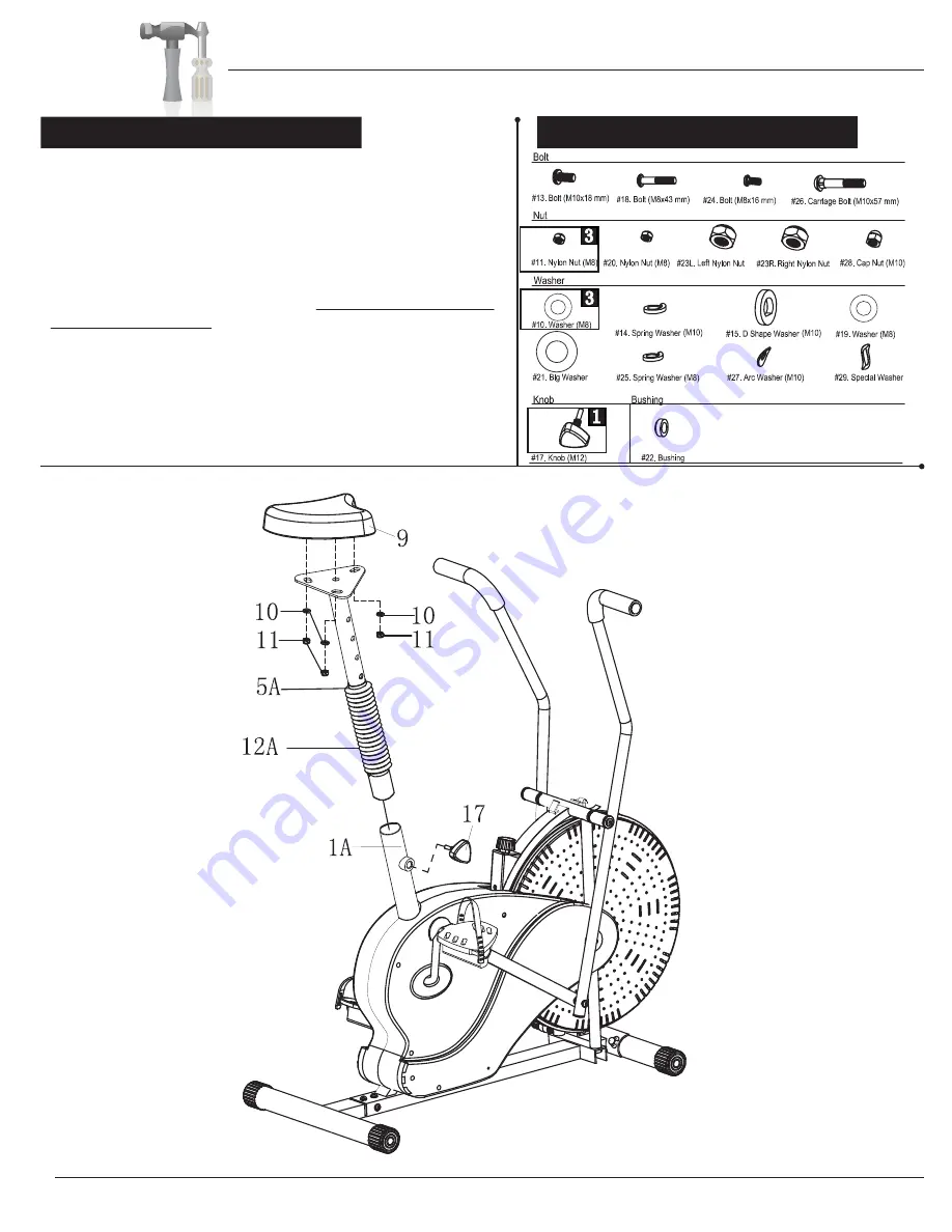
Remove the three Washers (#10) and three Nuts (#11) that
are pre-assembled on the Seat (#9). Then, attach the Seat (#9)
to the Seat Tube (#5A) and secure it with three Washers (#10)
and three Nuts (#11) that were previously removed.
Attach Bellows (#12A) to the Seat Tube (#5A) as shown in
illustration below.
Insert the Seat Tube (#5A) into the opening of the post that is
protruding from the Main Frame (#1A) a minimum of 4 inches to
engage the lowest hole. Please ensure that the hole on the Seat
Tube (#5A) is facing the same side as the hole located on the
Main Frame (#1A) and insert the Knob (#17) through the Main
Frame (#1A) post and through the hole on the Seat Tube (#5A).
Please refer to the illustration below. Always ensure that the
Knob (#17) is securely tightened and engaged through the hole on
the Main Frame (#1A) and the hole setting most comfortable to you
on the Seat Tube (#5A) for your safety.
Page 11


