3
Be careful to assemble all components
in the sequence they are presented.
NOTE:
Finger tighten all hardware in this step. Do Not wrench tighten until the end of step 3.
*Some parts are pre-installed.
A.
Attach Single Pulley Bracket (13) to Middle Plate (9) using:
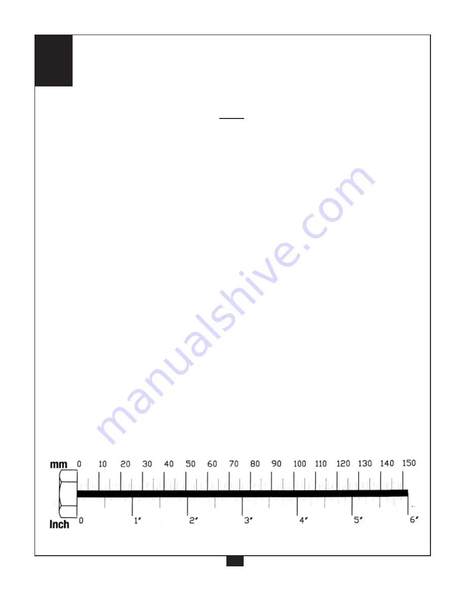
Two 29 (M8 x 20)
Two 36 (
f
8 washer)
Two 38 (M8 nylon lock nut)
B.
Attach Joint Assembly (D) and Middle Plate (9) to Mainframe Assembly (A) using:
Two 25 (M10 x 70 hex head bolt)
Four 35 (
f
10 washer)
Two 37 (nylon lock nut)
C.
Attach Single Pulley Assembly (14) to Sleeve Tube Assembly (E) using:
One 28 (M10 x 65 hex head bolt)
Two 35 (
f
10 washer)
One 37 (M10 nylon lock nut)
D.
Attach Sleeve Tube Assembly (E) through Joint Assembly (D) using:
Two 28 (M10 x 65 hex head bolt)
Four 35 (
f
10 washer)
Two 37 (nylon lock nut)
E.
Attach Sleeve Tube Assembly (E) to BodySolid G2, G3, G4, G5, G6, G10, GSTK Mainframe Tube
using:
Two 25 (M10 x 70 hex head bolt) *USE WITH G2, G3, G5, G6
Four 35 (
f
10 washer)
*USE WITH G4, G10, GSTK
Two 37 (M10 nylon lock nut)
One 11 (Bracket)
5
Summary of Contents for GFLP
Page 1: ...Assembly Instructions v 031008 B u i l t F o r L i f e GFLP ...
Page 3: ...1 2 ...
Page 5: ...2 4 ...
Page 7: ...3 6 BodySolid Mainframe Tube ...
Page 8: ...3A 7 BodySolid Mainframe Tube ...
Page 12: ...Exploded View Diagram GFLP ...


