background image

S T E P

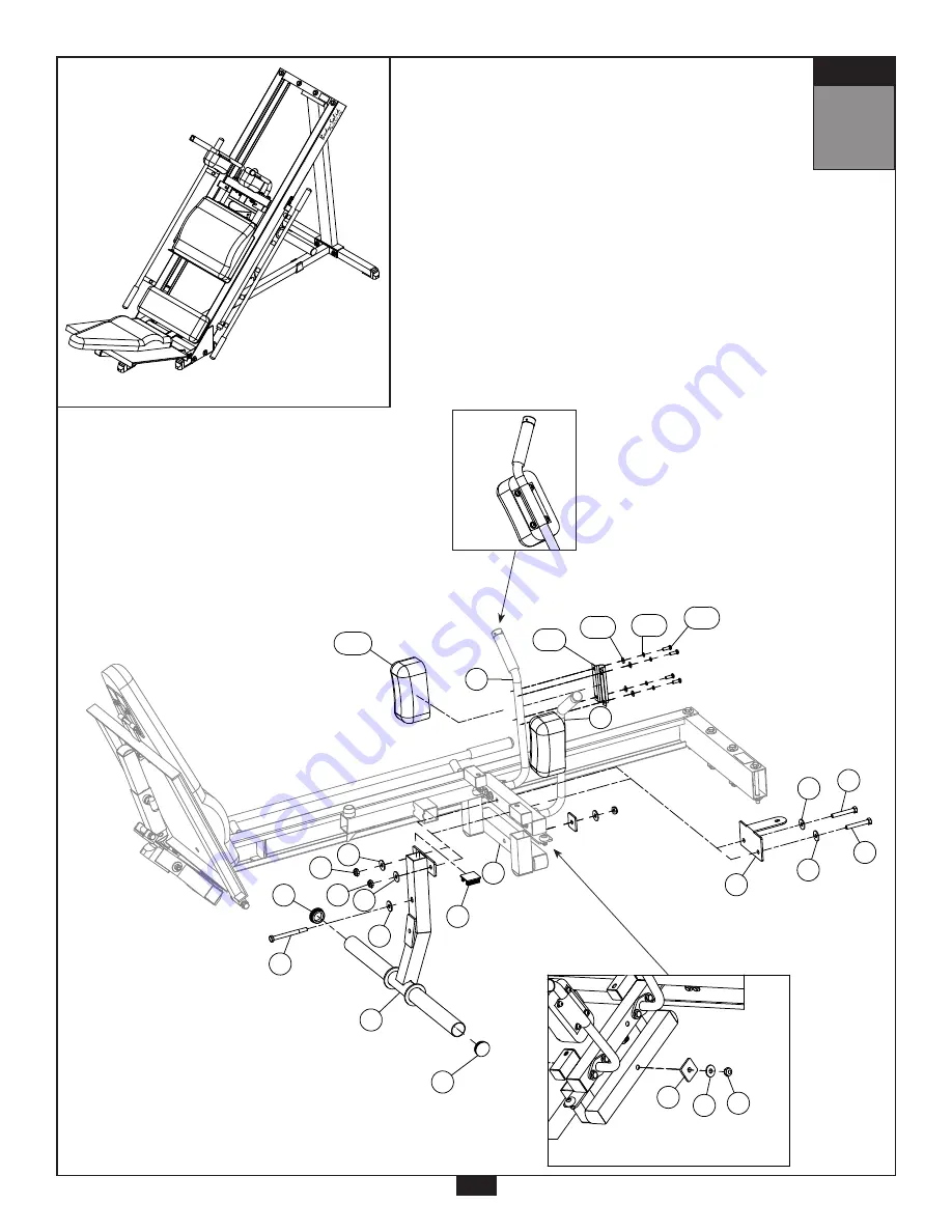
Above shows STEP 7
assembled and completed

Detail View

11

WX2

31

H

ABX2

22

18

18

22

31

4

J

22

29

V

22

18

22

2

22

2

R

Q

27X8

26X8

10X8

X

  23

S T E P

 7

Above shows Step 7 assembled and completed.

S T E P

Above shows STEP 7
assembled and completed

Detail View

11

WX2

31

H

ABX2

22

18

18

22

31

4

J

22

29

V

22

18

22

2

22

2

R

Q

27X8

26X8

10X8

X

by

by

®

®

Summary of Contents for GLPH1100

Page 1: ...renceDrawings p 3 ImportantSafetyInstructions p 4 BeforeYouBegin p 5 Dimensions p 6 SafetyGuidelines p 7 Preparations p 8 AssemblyInstructions p 9 25 Warning Safety Maintenance p 26 27 ExerciseTips p 28 47 TorsionSpringRemoval p 48 50 TorsionSpringInstallation p 51 53 MainframePartsList p 54 HardwareList p 55 Hardware ToScale p 56 59 ExplodedViewDiagram p 60 61 by GLPH1100 ...

Page 2: ...Diagram 1 Squat Press Diagram 2 Calf Press Position 1 Diagram 3 Calf Press Position 2 Diagram 4 Leg Press Position 1 Diagram 5 Leg Press Position 2 Diagram 6 Leg Press Position 3 The GLPH1100 has several adjustments that enable many different and effective workouts Please see below for a collection of GLPH1100 adjustment references by by by by by by by by by by by by ...

Page 3: ...e r e n c e D r a w i n g s Note Due to continuing product improvements specifications and designs are subject to change without notice Even though we have prepared this manual with extreme care neither the publisher nor the author can accept responsibility for any errors in or omission from the information given by by Note Due to continuing product improvements specifications and designs are subj...

Page 4: ...horoughly m Read each step in the assembly instructions and follow the steps in sequence Do not skip ahead If you skip ahead you may learn later that you have to disassemble components and that you may have damaged the equipment m Assemble and operate the GLPH1100 on a solid level surface Locate the unit a few feet from the walls or furniture to provide easy access The GLPH1100 is designed for you...

Page 5: ... 1 800 556 3113 for the dealer nearest you Body Solid continually seeks ways to improve the performance specifications and product manuals in order to ensure that only superior products are released from our factories Please take the time to carefully read through this manual thoroughly Instructions contained in this document are not intended to cover all details or variations possible with Body S...

Page 6: ...ace needed for the GLPH1100 could be more depending on the user Minimum Usage Space 2 11 7 8 4 7 Suggested Usage Space 10 5 gns are subject to he publisher nor the nformation given by by Note Due to continuing product improvements specifications and designs are subject to change without notice Even though we have prepared this manual with extreme care neither the publisher nor the author can accep...

Page 7: ...ight that is involved with the lift Keeping proper form also includes maintaining control through an entire range of motion m Breath properly Inhale during the eccentric phase of the exercise and exhale during the lifting or concentric phase Never hold your breath during any part of an exercise m Always wear the appropriate clothing and shoes when exercising Wearing comfortable athletic shoes with...

Page 8: ...elps keep it level A level machine has fewer malfunctions Provide ample space around the machine Open space around the machine allows for easier access Insert all bolts in the same direction For aesthetic purposes insert all bolts in the same direction unless specified in text or illustrations to do otherwise Leave room for adjustments Tighten fasteners such as bolts nuts and screws so the unit is...

Page 9: ...e pieces may have extra holes that you will not use Use only those holes indicated in the instructions and illustrations Do not fully tighten bolts until instructed to do so Note After assembly you should check all functions to ensure correct operation If you experience problems first recheck the assembly instructions to locate any possible errors made during assembly If you are unable to correct ...

Page 10: ...nsert two Foot Caps 32 into Right Stabilizer Frame C E Insert two End Caps 28 into Selector Insert Frame N F Make sure Pop Pin 17 is preinstalled into Selector Tube O G Set Selector Insert Frame N into Selector Tube O then secure Selector Tube O to Base Frame A using One 3 M12x90 hex head bolt Two 21 M12x25 washer One 18 M12 nylon lock nut H Connect Right Stabilizer Frame C and Left Stabilizer Fra...

Page 11: ... completed Above shows STEP 1 assembled and completed D5 D5 D B1X2 C2X2 B1 C1 C1 A3 C2X2 D7 A2X2 D5 D5 C O D1X2 N A D5 A17 S T E P Above shows STEP 1 assembled and completed 34 32 21 34 32 32 28 N O 17 D 18 21 22 18 28 3 22 2 2 32 C 32 18 22 A 22 ...

Page 12: ...into Carriage H C Insert two End Caps 29 into Carriage H D Insert four End Caps 30 into Carriage H E Unscrew both Allen Screws 13 from Carriage H to loosen Shaft 48 F Slide Shaft 48 out of Carriage H G Connect Adjustable Plate K to Carriage H by using Two 41 copper spacer One 48 shaft One 45 torsional spring One 46 torsional spring NOTE Make sure Torsion Springs 45 and 46 are inserted as shown H T...

Page 13: ...pre installed g sticker 9440 217 pre installed g sticker 9440 208 pre installed 30 31 32 33 34 37 38 39 40 4 45 46 48 41 2PCS 3PCS 4PCS 2PCS 7PCS 8PCS 2PCS 2PCS 1PCS 4PCS 4PCS 2PCS 8PCS 2PCS 4PCS 2PCS 2PCS 1PCS 1PCS 2PCS 1PCS 8PCS 2PCS 1PCS 2PCS 1PCS 1PCS 1PCS 1PCS 1PCS 1PCS torsional spring DetailView 30 30 29 38 38 39 45 46 48 30 H 13 ed 6 torsional spring DetailView 30 30 29 38 38 39 45 46 41 4...

Page 14: ...Left Glide Frame G and Right Glide Frame F NOTE Secure Rubber Pads 35 as shown in the diagram D Slide Carriage H into Left Glide Frame G and Right Glide Frame F NOTE Carriage H is extremely heavy Two people are required for this installation E Insert two Foot Caps 32 into Base Cross Bar E F Connect Upright B to Base Cross Bar E and Base Frame A using Two 2 M12x80 hex head bolt Four 22 M12 washer T...

Page 15: ...5 22 E 22 2 22 2 15 S T E P 3 Above shows Step 3 assembled and completed S T E P Above shows STEP 3 assembled and completed 22 18 22 18 22 1 1 1 22 22 18 22 22 22 35 5 22 22 18 35 18 1 C D 22 18 G F 32 22 22 A 18 18 35 32 B H 22 18 22 18 AD 4 22 4 22 5 22 E 22 2 22 2 Page GLPH 1100 2 062008 D8 F A1 C2 A1 C2 C2 B1 C2 D8 B1 B1 C2 D8 B1 C2 C2 A1 C2 A1 STEP 1 7 by by by by ...

Page 16: ...End Caps 33 into Left Adjustment Bar M as shown E Slide the short end of Right Adjustment Bar L into the round insert bracket on Right Glide Frame F as shown in the diagram NOTE A detailed view of the long and short Adjustment Bar ends are shown in the figure on the next page F Insert the long end of Right Adjustment Bar L into Slide Tube P then secure Slide Tube P onto Right Glide Frame F using T...

Page 17: ...S T E P 4 Above shows Step 4 assembled and completed S T Above shows STEP 4 assembled and completed 3 21 21 18 3 21 short long long short 21 18 21 18 21 Round Insert Bracket S N M L H 8 25 8 25 PX2 25 20 20 25 37X4 33X4 F 3 D C 33X4 G Above shows STEP 4 assembled and completed S L M A8X4 C5X8 B3X4 PX2 D10X4 D6X4 A3 A3 C1 C1 B1 A3 C1 short long G F long short D N C1 B1 C1 B1 C C1 Short End Long End...

Page 18: ...ip the T nuts pressed into the wood B Attach Rubber Pad 36 to Lower Pad AA NOTE See figure on next page for a detailed view C Slide Left Lower Mount Frame T and Right Lower Mount Frame U onto the rod on Foot Plate S and secure Left Lower Mount Frame T and Right Lower Mount Frame U onto Lower Pad AA using Four 10 5 16 x 1 round allen head bolt Four 26 M8 spring washer Four 25 M8 washer Note Do not ...

Page 19: ... AA T 36 S 25 26 10 25 26 10 U 25 26 10 K 9 9 9 9 Above shows Step 5 assembled and completed S T E P Above shows STEP 5 assembled and completed Y 25 26 10 36 AA T 36 S 25 26 10 25 26 10 U 25 26 10 K 9 9 9 9 Above shows assembled an Y 36 AA Lower Pad Underside by by by by ...

Page 20: ...her Two 25 M8 washer NOTE See correct installation direction in diagram Do not over tighten Pad Bolts 11 over tightening will strip the T nuts pressed into the wood B Connect Left Arm Q to Carriage H and secure using Two 7 M10x75 hex head bolt Five 24 M10 washer Two 19 M10 nylon lock nut One 6 M10x20 hex head bolt C Connect Right Arm R to Carriage H and secure using Two 7 M10x75 hex head bolt Five...

Page 21: ...F 19X2 6X2 24X2 24X2 7X2 7X2 Q R H by by STEP 6 nd completed R Q C4X2 A7X2 C4X2 A7X2 C5X2 C6X2 A11X2 B2X2 A6X2 B2X2 C4X2 C4X2 C4X2 all Detail View Detail View G Above shows STEP 6 assembled and completed 10 R C5X2 C6X2 A11X2 B2X2 A6X2 B2X2 C4X2 C4X2 C4X2 AC l o n g s h o r t direction to install F Detail View G S T E P Above shows STEP 6 assembled and completed 24X2 19X2 24X2 24X2 l o n g s h o r ...

Page 22: ...ht Horn Bar J to Carriage H by adding One 4 M12x125 hex head bolt Two 22 M12 washer One V Support Plate One 18 M12 nylon lock nut E Connect Arm Pad AB and Pad Frame W to Left Arm Q using Four 10 5 16 x 1 round allen head bolt Four 26 M8 spring washer Four 27 M8 washer Note Do not over tighten Pad Bolts 10 over tightening will strip the T nuts pressed into the wood F Connect Arm Pad AB and Pad Fram...

Page 23: ... ABX2 22 18 18 22 31 4 J 22 29 V 22 18 22 2 22 2 R Q 27X8 26X8 10X8 X 23 S T E P 7 Above shows Step 7 assembled and completed S T E P Above shows STEP 7 assembled and completed Detail View WX2 31 H ABX2 22 18 18 22 31 4 J 22 29 V 22 18 22 2 22 2 R Q 27X8 26X8 10X8 X by by ...

Page 24: ...ing washer Two 25 M8 washer Note Do not over tighten Pad Bolts 12 over tightening will strip the T nuts pressed into the wood B Connect Head Rest Pad Z to Weight Horn Bar Support Plate X using One 10 5 16 x 1 round allen head bolt One 26 M8 spring washer One 25 M8 washer Note Do not over tighten Pad Bolt 10 over tightening will strip the T nut pressed into the wood C Congratulations The assembly o...

Page 25: ...8 Above shows Step 8 assembled and completed S T E P Above shows STEP 8 assembled and completed 25X2 26X2 12X2 Z X H 25 26 10 S T E P Above shows STEP 8 assembled and completed 25X2 26X2 12X2 Z X H 25 26 10 by by ...

Page 26: ... end users of proper usage m Be sure all supervisors and personal trainers who instruct end users on equipment use are properly trained and know the function and importance of every adjustment and setting Also be sure these trainers provide proper instruction to end users on the fundamentals of strength training UPHOLSTERY m Wipe down after every workout m Periodically take the time to use a mild ...

Page 27: ...LSTERY WIPE DOWN AND DRY CLEAN AND CONDITION FRAME WIPE DOWN AND DRY POLISH WAX CHROME WIPE DOWN AND DRY POLISH LUBRICATE NUTS BOLTS FASTENERS TIGHTEN AND OR ADJUST AS NEEDED GUIDE RODS LUBRICATE AND CLEAN LINEAR RODS LUBRICATE AND CLEAN SEAT SLEEVES LUBRICATE AND CLEAN ADJUSTMENTS LOCKING PINS TIGHTENING KNOBS WEIGHT STACK PINS WARNING INSTRUCTION LABELS SPRINGS POP PINS ANTI SKID SURFACES HAND G...

Page 28: ...dequate EXERCISE LARGE MUSCLES FIRST You should work your large muscle groups first ie squat bench press lat pulldown before you exercise your small muscle groups ie bicep curls tricep pressdowns lateral raises EXERCISE PROGRAM DURATION A weight training routine should take anywhere from 45 minutes to one hour to complete Add another 20 to 60 minutes when you include stretching warm up aerobics an...

Page 29: ... muscles a chance to partially recover before working them again For power and muscle size development allow a 3 to 4 minute rest interval between sets For muscular endurance and definition allow a 30 second rest interval For strength training allow a 60 to 90 second rest interval RISK SHOULD NOT EXCEED BENEFIT If the risk of a specific exercise exceeds its potential benefit it is best to stay on ...

Page 30: ...efore must be ingested Plant sources of protein such as beans starchy vegetables nuts and grains do not always contain all eight amino acids Because of this vegetarians must consume a variety of protein containing foods It is recommended that proteins make up 10 to 15 of one s daily calories This will ensure adequate protein for growth maintenance and the repair of cells Protein requirements for a...

Page 31: ...longer resting period between sets The results of using this method are normally increased muscular strength and mass If the desired outcome is to gain overall muscle mass your exercise prescription should lean toward a higher weight resistance doing 2 to 6 repetitions per set with a rest period of 3 to 4 minutes between each set Rest Periods Between Workouts The amount of rest between training se...

Page 32: ...ild up of lactic acid in the muscle fibers This is the result of intense exercise Muscle soreness can become a problem when the body is pushed too fast and too quickly As a beginner tendons ligaments joints and tissues have not yet developed the ability necessary to recover from high intensity exercise A general warm up of stretching and light calisthenics prior to exercise can possibly reduce the...

Page 33: ... Rest Between Workouts If you re still sore from your previous workout you don t have to go back at it just because it s your scheduled day Give your body an extra day off to fully recover so when you return you will be able to give 100 6 Overtraining It s not how much time you spend working out but what you accomplish that really matters Try to keep your resistance workouts within 45 to 60 minute...

Page 34: ...nd cool down periods You may have to modify your current lifestyle to accommodate your new schedule It s very important to include the following basic components to achieve successful results Muscular Endruance Definition Increase Power Muscle Mass Increase Strength Stretching Weight Training Aerobic Exercise Nutrition If your personal goals involve losing a considerable amount of body fat you wil...

Page 35: ...st period between sets should be from 60 to 90 seconds This allows a degree of muscle recovery before you hit them again FOR POWER AND MUSCLE MASS This is the method most often used by bodybuilders and is recommended only for the intermediate and advanced lifter The weights used are heavy this shocks the muscles and stimulates a more rapid increase in muscle size Usually exercises are performed fo...

Page 36: ...d supinate your wrist The ability to build your biceps peak is largely genetic but exercises that maximally stress the short head will help BICEPS STANDING BICEP CURL SEATED BICEP CURL INCLINE CURL PREACHER CURL CONCENTRATION CURL ONE ARM CABLE CURL FOREARMS WRIST CURL REVERSE WRIST CURL ABDOMINALS The rectus abdominus has upper and lower regions but you can t isolate one area over the other Still...

Page 37: ...uteus Medius Gluteas Maximus Abs External Oblique Triceps Triceps Brachii lateral head longhead medial head Hamstrings Iliotibial Band Biceps Femoris Adductor Magnus Semitendinosus Gracilis Semimembranosus Abs Serratus Anterior External Oblique Rectus Abdominis Tendinous Inscriptions Thighs Sartorius Pectineus Adductor Longus Gracilis Tensor Fasciae Latae Calves Gastrocnemius Peroneus Longus Tibia...

Page 38: ...38 ...

Page 39: ...39 Make several copies of this page to keep track of your progress You can print more copies of this page by going to http www bodysolid com support docs html ...

Page 40: ...40 Make several copies of this page to keep track of your progress You can print more copies of this page by going to http www bodysolid com support docs html ...

Page 41: ...41 Make several copies of this page to keep track of your progress You can print more copies of this page by going to http www bodysolid com support docs html ...

Page 42: ...st popular type of stretching is the static stretching technique This form of stretching involves voluntary complete relaxation of the muscles while they are elongated A static stretch is a constant steady stretch in which the end position is held for 10 to 30 seconds This technique is popular because it is easy to learn effective and accompanied by minimal soreness with the least risk of injury B...

Page 43: ...le continuing to reach upward slowly reach slightly backward 5 Hold for 10 seconds LOWER BACK Spinal Twist Pretzel MUSCLE S AFFECTED internal oblique external oblique and spinal erectors 1 Sitting with legs straight and upper body nearly vertical place right foot on left side of left knee 2 Place back of left elbow on right side of right knee which is now bent 3 Place right palm on floor 12 to 16 ...

Page 44: ... Standing place both arms behind back 2 Interlock fingers with palms facing each other 3 Straighten arms fully 4 Slowly raise the straight arms 5 Hold for 10 to 15 seconds 6 Keep head upright and neck relaxed Stretching shoulder joints sitting Stretching the chest STRETCHING WARM UP COOL DOWN SIDES Side Bend with Straight Arms MUSCLE S AFFECTED external oblique latissimus dorsi and serratus anteri...

Page 45: ...body nearly vertical and legs straight 2 Lean forward from waist and grasp toes with each hand slightly pull toes towards the upper body and pull chest towards leg If you are very stiff try to grasp the ankles Hold for 10 seconds 3 Release toes and relax foot 4 Grasp ankles and continue to pull chest towards legs Hold for 10 seconds 5 Still grasping the ankles point away from body and continue to ...

Page 46: ...er body nearly vertical and legs straight and spread legs as far as possible 2 With right hand grasp toes of right foot and pull on toes slightly while pulling chest toward right leg Hold for 10 seconds 3 Release toes and relax foot 4 Grasp ankle and continue to pull chest toward right leg Hold for 10 seconds 5 Point toes away from body and continue to pull chest toward right leg Hold for 10 secon...

Page 47: ...o 4 inches high 2 Place balls of both feet on the step or board 1 inch from its edge 3 With straight legs lower heels as far as posible 4 Hold for 10 to 15 seconds 5 To stretch achilles tendon raise heels slightly Slightly flex the knees and then lower the heels This stretch will be felt in the achilles tendon 6 Hold for 10 to 15 seconds 7 For a more intense and individualized stretch perform this...

Page 48: ...move the M12x135 Hex Head Bolt 5 as shown or if Shaft 48 is not threaded as shown in the figure skip this step Thread the M12x135 Hex Head Bolt 5 onto Shaft 48 and leave it finger tight or if Shaft 48 is not threaded then use a punch or other tool that can be used to push out Shaft 48 48 ...

Page 49: ...ad of the threaded bolt or punch Continue using a hammer until the bolt or punch ter minates near the axis open ing or Shaft 48 is protrud ing out of the opposite end Unscrew and remove the bolt ifthismethodhasbeen used Remember to reinstall the bolt back onto the GLPH1100 mainframe 49 ...

Page 50: ...p r i n g R e m o v a l Remove Shaft 48 by rotat ing and pulling it out of the axis of rotation Lubricationmayberequired for this procedure Carefully lift Adjustable Plate K away from the GLPH1100 Remove both Torsion Springs 45 46 50 ...

Page 51: ... the long side of Tor sion Springs 45 46 into the rear hole of Adjustable Plate K Insert the short side of the Torsion Springs 45 46 into the square frame on Carriage H as shown Insert Shaft 48 into the first section of the axis Lubrication may assist with this procedure 51 ...

Page 52: ...s i o n S p r i n g I n s t a l l a t i o n Push Shaft 48 inward mak ing sure that both axis are alligned Torsion Springs 45 46 will need slight alignment while Shaft 48 is being in serted Use a hammer to aid the process 52 ...

Page 53: ...rst Torsion Spring tap on the secondTorsion Spring to bring it into alignment with the axis of rotation Use a hammer to continue inserting Shaft 48 Make sure the remainder of Carriage H is aligned and continue to insert Shaft 48 Upon completion tighten the two Set Screws 13 to secure Shaft 48 53 ...

Page 54: ...ht Adjust Bar M 1 Left Adjust Bar N 1 Selector Insert Frame O 1 Selector Tube P 2 Slide Tube Q 1 Left Arm R 1 Right Arm S 1 Foot Plate T 1 Left Lower Mount Frame U 1 Right Lower Mount Frame V 1 Support Plate 8312 013 W 2 Pad Frame 8343 023 X 1 Weight Horn Bar Support Plate 8333 045 Y 1 Upper Pad 9112 026 Z 1 Head Rest Pad 9132 016 AA 1 Lower Pad 9112 025 AB 2 Arm Pad 9132 002 AC 1 Middle Pad 9122 ...

Page 55: ... FOOT CAP 2 x 2 9211 024 33 8 ROUND END CAP Ø20 9211 036 34 2 BASE CAP 2 x 2 9212 010 35 2 RUBBER PAD M38x75 9310 002 36 1 RUBBER PAD M38x325 9310 042 37 4 ROUND END CAP 1 x 2 5T 9260 021 38 4 END CAP M38x38 9211 003 39 2 END CAP M25x50 9211 009 40 8 BEARING 8510 002 PREINSTALLED 41 2 COPPER SPACER 8520 013 42 4 CONVEXITY LOOP 9213 050 PREINSTALLED 43 2 CHROME COLLAR Ø35xØ26X19L 8890 061 PREINSTAL...

Page 56: ...n a c t u a l s i z e KEY A1 HEX HEAD BOLT M12 X 75 PARTIAL THREAD QTY 4 KEY A2 HEX HEAD BOLT M12 X 80 PARTIAL THREAD QTY 6 KEY A3 HEX HEAD BOLT M12 X 90 PARTIAL THREAD QTY 4 KEY A5 HEX HEAD BOLT M12 X 135 PARTIAL THREAD QTY 2 KEY A4 HEX HEAD BOLT M12 X 125 PARTIAL THREAD QTY 3 KEY A6 HEX HEAD BOLT M10 X 20 PARTIAL THREAD QTY 2 Part 4 M12x125 Hex Head Bolt Partial Thread Qty 3 G L P H 1 1 0 0 H A ...

Page 57: ...PARTIAL THREAD QTY 4 KEY A8 HEX HEAD BOLT M8 X 20 FULL THREAD QTY 4 KEY A9 Co Noid Head Bolt 5 16 X 1 FULL THREAD QTY 4 KEY A10 ROUND BOLT 5 16 X 1 PARTIAL THREAD QTY 13 KEY A11 HEX HEAD BOLT 5 16 X1 1 4 FULL THREAD QTY 2 G L P H 1 1 0 0 H A R D W A R E s h o w n i n a c t u a l s i z e KEY A12 HEX HEAD BOLT 5 16 X2 1 4 FULL THREAD QTY 2 KEY A13 ALLEN SCREW M8 X 8 FULL THREAD QTY 2 pre installed P...

Page 58: ... 22x78L 8250 012 QTY 1 pre installed Part 12 5 16 x 2 1 4 Hex Head Bolt Full Thread Qty 2 KEY A11 HEX HEAD BOLT 5 16 X1 1 4 FULL THREAD QTY 2 KEY A12 HEX HEAD BOLT 5 16 X2 1 4 FULL THREAD QTY 2 KEY A13 ALLEN SCREW M8 X 8 FULL THREAD QTY 2 pre installed 1b Part 18 M12 Nylon Lock Nut Qty 19 G L P H 1 1 0 0 H A R D W A R E s h o w n i n a c t u a l s i z e KEY B1 NYLON LOCK NUT M12 QTY 19 KEY B2 NYLO...

Page 59: ... r d w a r e T o S c a l e Part 21 M12 Φ25 Washer Qty 8 Part 22 M12 Φ34 Washer Qty 30 Part 24 M10 Φ27 Washer Qty 10 Part 25 M8 Φ24 Washer Qty 17 Part 26 M8 Spring Washer Qty 25 Part 27 M8 Φ18 Washer Qty 12 59 ...

Page 60: ...2 15 26 26 27 10 27 26 27 26 24 19 24 10 26 27 10 10 7 7 26 27 10 26 10 26 7 24 7 24 24 19 24 6 24 19 44 15 15 AB 14 49 13 40 12 20 49 49 31 22 10 10 4 W 24 24 27 W 27 AB R 60 21 18 11 35 25 EXPLODED VIEW DIAGRAM GLPH1100 3 21 C 40 47 12 27 26 38 38 40 60 40 22 6 31 29 9 9 18 22 18 22 22 22 18 18 22 18 21 22 4 22 9 50 22 37 33 33 51 Y 41 55 K 28 N 3 Z 60 45 46 49 40 39 47 52 16 58 H 9 O 52 17 32 A...

Page 61: ...opyright 2010 Body Solid All rights reserved Body Solid reserves the right to change design and specifications when we feel it will improve the product Body Solid machines maintain several patented and patent pending features and designs All rights reserved on all design patents and utility patents by ...

Reviews: