background image

T5

206

220

209

223

225

207

L3

223

T3

209

207

225

203

209

223

225

T2

209

234

223

225

202

L1

220

202

L4

223

225

209

203

T4

209

223

225

202

L2

T1

T2

T3

L2

202

203

L1

T4

L3

T5

L4

STEP  4    

Top Cable & Low Cable Assembly

223

220

203

225

209

T1

7

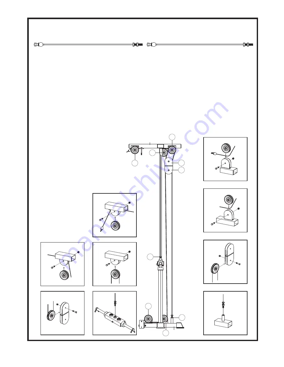
TOP  CABLE (220)

LOW  CABLE (234)

Assemble cables and pulleys simultaneously 

Top Cable.


1. Insert the screw end of the Top Cable (220) 

into the slot in the front of the Top Frame (203).  

Slide it through the inside of the Top Frame 

(203), and then out of the slot in the rear.

2. Insert Pulleys into the bracket at these slots 

with cable running above as shown in Figs T1 

and T2.  Secure the pulleys with one 3/8" X 1- 

3/4" Hex Bolt (223) and one 3/8" Nylon Nut 

(225) each.

3. Route the cable down and around top pulley 

(T3) ( secure with one 3/8" X 1-3/4" Hex Bolt 

(223) and one 3/8" Nylon Nut (225) ) in

    the Double Pulley Block (207) as shown

    in Fig.T3. 

4. Continue routing over a pulley in the 

    bracket in the Top Frame (203) as

    Fig T4. and then down to the Top Plate (206).  

Screw the threaded end of the Top Cable (220) 

into the Top Plate (206)

 AT LEAST

 one third of 

the way. This is a cable adjustment area. When 

all cable have been

    tightened, make sure

    to secure the Jam Nut

    to prevent the Top

    Cable (220) from

    unscrewing.

Low Cable


Route the ball end of the Low Cable (234) under 

two pulleys on Weight Base (202) as shown Figs 

L1 and L2..  The route Low Cable (234) up and 

over bottom pulley (L3) in Double Pulley Block 

(207) as Fig. L3.  Continue down to the threaded 

frame extension welded in Weight Base (202) as 

Fig L4..  This is a cable adjustment area.  When 

all cable have been tightened, make sure to 

secure the Jam Nut to prevent the Low Cable 

(234) from unscrewing. 

Summary of Contents for 5042

Page 1: ...r we are committed to your complete satisfaction If you have questions or find missing or damaged parts we will guarantee your complete satisfaction through our authorized dealer service centers or our home office customer service department Please call your local dealer for assistance or BodyCraft at 800 990 5556 9 00 AM 5 00 PM Our trained technicians will provide immediate assistance to you fre...

Page 2: ...h or abrasive chemicals 3 Inspect and tighten all parts before every use Replace any worn parts immediately Failure to do so may result in serious injury 4 Keep children away from the JONES MACHINE at all times 5 Keep your hands away from cables and pulleys during operation Keep your hands away from moving parts other than the designated handles 6 When adjusting the seat make sure the spring pin i...

Page 3: ... 224 211 205 212 204 213 220 209 209 225 225 210 234 224 220 211 224 233 225 225 225 224 223 229 231 229 231 209 225 225 230 230 228 227 227 232 223 206 221 202 224 201 222 224 225 222 223 218 219 225 223 203 214 218 218 217 215 216 216 226 217 215 214 213 207 225 223 213 233 ...

Page 4: ...sembled on Top Plate RUBBER CUSHION 1 SPRING CLIP 1 1 4 HAND GRIP pre assembled on Curl Bar 1 1 4 X 140mm ROUND HAND GRIP pre assembled on Curl Bar 1 T SHAPE END PLUG pre assembled on Curl Bar SNAP HOOK CHAIN LINKS TOP CABLE TOP PLATE BOLT 3 8 X 3 HEX BOLT 3 8 X 1 3 4 HEX BOLT 3 8 WASHER 3 8 NYLON NUT CURL BAR LAT BAR HOOK PLATE ASSEMBLED ON LAT BAR COLLAR ASSEMBLED ON LAT BAR SEALING RING ASSEMBL...

Page 5: ...3 4 55 55 42 42 51 51 51 51 51 55 51 51 51 51 51 55 42 42 201 A B STEP 1 4 To ease assemble do NOT tighten any bolt until instructed Remove the flat Base Connector 4 on your Jones Smith and replace it with your new square Rear Stabilizer 201 Reuse the hardware ...

Page 6: ...ht Base 202 3 Insert the two Guide Rods 205 into the holes in Weight Base 202 and slide two Stack Spacers 204 two Rubber Cushions 213 over top and down the Guide Rod 205 IF YOU HAVE PURCHARSED THE OPTIONAL F200 WEGIHT STACK UPGRADE KIT Do not use the Stack Spacers provided if you have purchased Optional F200 weight stack Instead use the Stack Spacers provided in the F200 kit 4 Slide the Top Plate ...

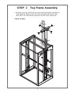
Page 7: ... 6 210 210 210 203 205 225 224 7 210 233 224 224 1 Slide the Top Frame 203 over top of the Guide Rod 205 and attach it to the Rear Top Frame 7 of The Jones using two 3 8 X 2 3 4 Hex Bolts 233 four 3 8 Washers 224 and two 3 8 Nylon Nuts 225 Tighten all Bolts ...

Page 8: ...d top pulley T3 secure with one 3 8 X 1 3 4 Hex Bolt 223 and one 3 8 Nylon Nut 225 in the Double Pulley Block 207 as shown in Fig T3 4 Continue routing over a pulley in the bracket in the Top Frame 203 as Fig T4 and then down to the Top Plate 206 Screw the threaded end of the Top Cable 220 into the Top Plate 206 AT LEAST one third of the way This is a cable adjustment area When all cable have been...

Page 9: ...n all bolts are tightened securely For better performance apply a household lubricant such as silicone to GUIDE RODS 205 Enjoy many years of a Fit Lifestyle Thank you for purchasing the Jones Machine System If You have any questions please call your local BodyCraft dealer or call our customer service department at 800 990 5556 8 ...

Reviews: