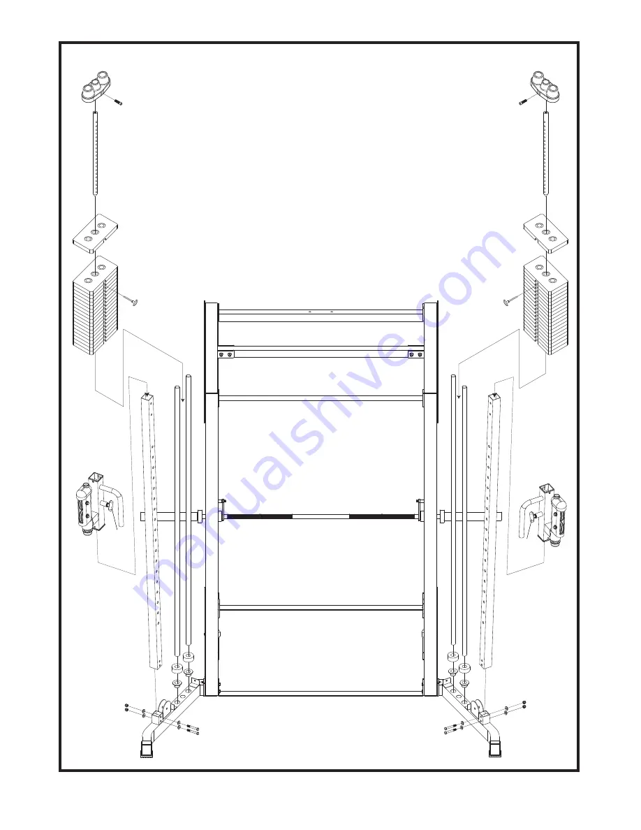
STEP 2 Weight Base Assembly
5
407R
423
408L
433
433
438
438
429
428
428
414
414
435
435
417
417
410
410
418
418
424
424
415
415
429
401R
402L
438
438
441
441
1. Attach Upright Frame (415) to the Right Base Frame (401R), using two 3/8"
X 2-3/4" Hex Bolts (433), four 3/8" Washers (438) and two 3/8" Nylon Nuts
(441).
2. Insert two Guide Rod Holders (429) to the Right Base Frame (401R) as
shown.
3. Insert the two Guide Rods (414) into the Guide Rod Holders (429) in the
Right Base Frame (401R) and slide two Rubber Donuts (428) over top and
down the Guide Rods (414).
4. Slide the 10 lbs plate (418) {19 per side} over top and down the Guide Rod
(414). Make certain that each plate is oriented with selector hole on bottom
and facing forward. Attach the Top Plate (435) to the Selector Rod (410)
using the Top Plate Bolt (435). Tighten Top Plate Bolt (435) with Hex
Wrench (not provided). Screw the Pulley Bracket (409) into the Selector
Rod (410), only about half way. This will be an adjustment point in the
future. Slide Top Plate (417) over and down to the Guide Rods (414).
5. Slide the Right Cable Height Adjuster (407R) over the top of the Upright
Frame (415). Stop at your desired height by locking the Pop Pin (423).
423


