background image

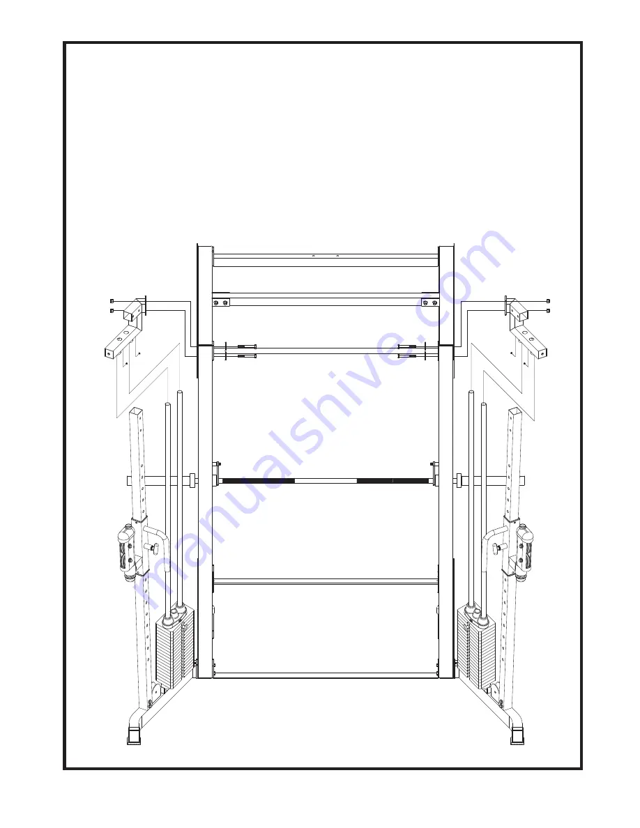
STEP  3    Top Frame Assembly

6

403R

404L

415

414

415

414

2

2

437

437

447
447

51

51

447

51

55

55

447

6

51

1. Loosen the pre-assembled two 5/16" X 1/4" Set Screws (437) in the ringlets on 

the Top Frame (403R) to allow it to easily slide onto the Guide Rods (414).  Slide 

the Top Frame (403R) onto the Guide Rods (414).  Attach Right Top Frame 

(403R) to Front Top Frame (2) of the Jones, re-using the two 3/8" X 4-1/4" Hex 

Bolts (447), two 3/8" Washers (51) and two 3/8" Nylon Nuts (55) originally used 

on the base Jones. Repeat for left side.

Tighten all Bolts.

Summary of Contents for 50442

Page 1: ...y home gym supplier we are committed to your complete satisfaction If you have questions or find missing or damaged parts we will guarantee your complete satisfaction through our authorized dealer ser...

Page 2: ...or abrasive chemicals 3 Inspect and tighten all parts before every use Replace any worn parts immediately Failure to do so may result in serious injury 4 Keep children away from the JONES MACHINE at...

Page 3: ...0 446 446 420 408L 407R 419 419 416 419 442 442 421 416 419 442 421 412 412 442 425 425 440 426 422 422 402L 401R 431 425 425 440 426 431 411 411 432 406L1 405R2 405R1 406L2 441 441 438 432 438 438 43...

Page 4: ...led SELECTOR PIN BEARING END CAP PLASTIC BUSHING RUBBER DONUT PLASTIC GUIDE ROD HOLDER BUSHING STEEL SPACER 3 8 X 3 HEX BOLT 3 8 X 2 3 4 HEX BOLT 3 8 X 1 3 4 HEX BOLT TOP PLATE BOLT 5 16 X 1 2 HEX THR...

Page 5: ...for a right side component please duplicate procedure for the left side 2 Remove two 3 8 X 4 Hex Bolts 42 on your Jones and attach Right Base Frame 401R to The Jones Reuse the hardware two 3 8 X 4 Hex...

Page 6: ...Rubber Donuts 428 over top and down the Guide Rods 414 4 Slide the 10 lbs plate 418 19 per side over top and down the Guide Rod 414 Make certain that each plate is oriented with selector hole on bott...

Page 7: ...n the ringlets on the Top Frame 403R to allow it to easily slide onto the Guide Rods 414 Slide the Top Frame 403R onto the Guide Rods 414 Attach Right Top Frame 403R to Front Top Frame 2 of the Jones...

Page 8: ...8 438 406L1 406L2 405R2 405R1 403R 404L 438 438 438 438 438 432 1 Attach Right Top Panel 405R1 405R2 to the Right Top Frame 403R as shown using five 3 8 X 3 Hex Bolts 432 ten 3 8 Washers 438 and five...

Page 9: ...le 416 between the pulleys in the front of the Right Cable Height Adjuster 407R as shown Fig R1 Route the cable up and over two top Pulleys at the Front and Rear of the Top Panel 405 as shown Fig R2 R...

Page 10: ...416 between the pulleys in the front of the Left Cable Height Adjuster 408L as shown Fig L1 Route the cable up and over two top Pulleys at the Front and Rear of the Top Panel 406 as shown Fig L2 L3 t...

Page 11: ...colse to Jones 446 446 446 412 436 439 436 439 412 436 439 436 439 1 Attach Front Rear Stack Shroud 412 413 and Trim for Shroud 446 to the Right Top Frame 403R and Right Base Frame 401R using four 5...

Page 12: ...take the following steps before using the Jones Cable Functional Trainer Attachment 1 Make certain all bolts are tightened securely 2 For better performance apply a household lubricant such as silico...

Reviews: