


B13
A12
Assembly
4
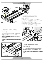
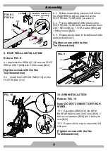
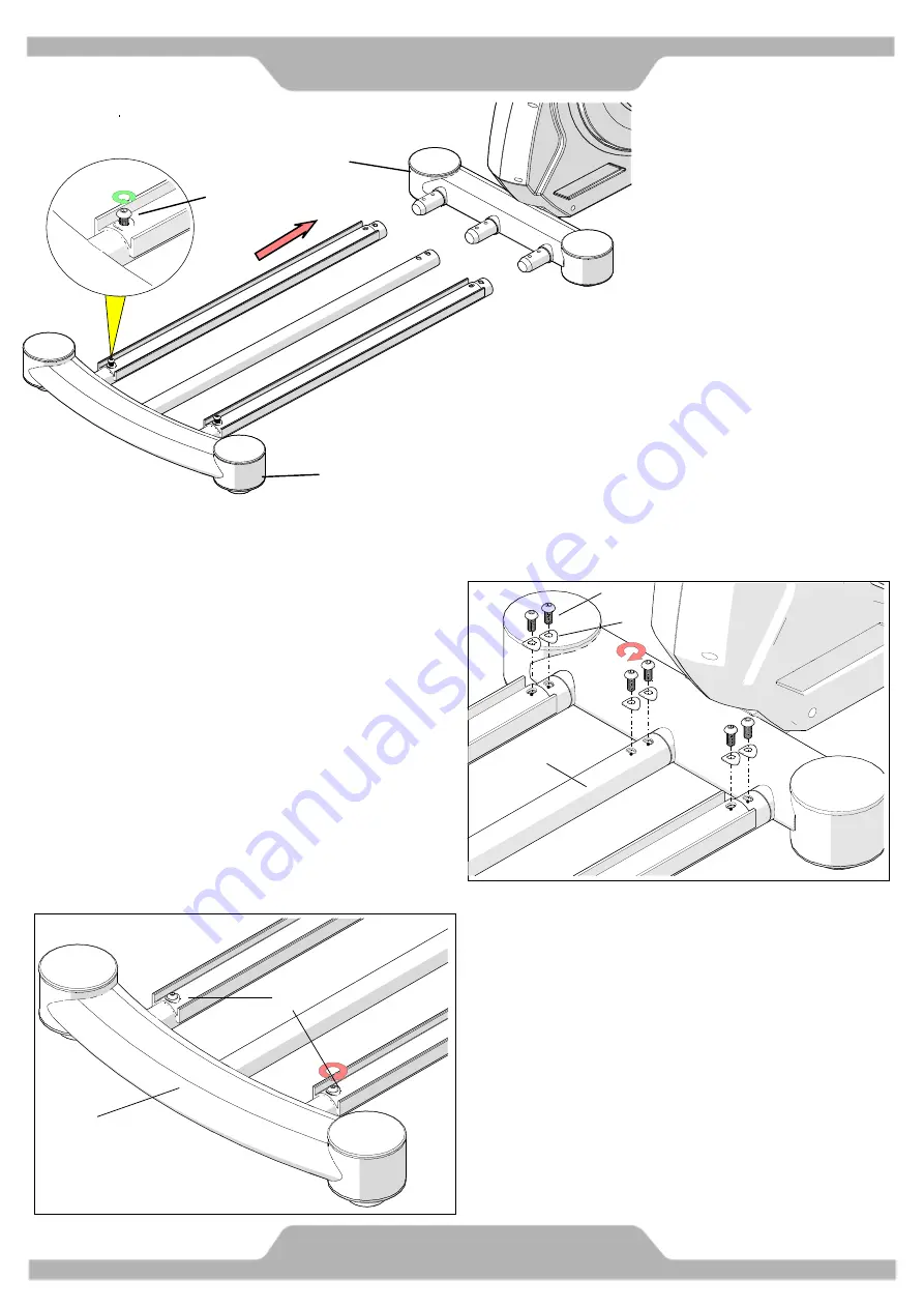
1. GUIDE RAIL INSTALLATION
Refer to Fig. 1
1.1 Slightly loosen the 2 M8 Screws [B13] at
the rear of the GUIDE RAIL [A12] using the M5
Allen Key provided. Fig. 1.1 in Fig.1.
1.2 Install the the GUIDE RAIL [A12] onto the
rear tube of the MAIN FRAME [A01].
FIG. 1
FIG. 1.1
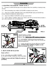
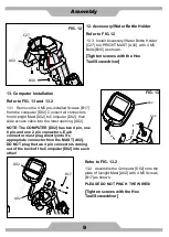
FIG. 2
B13
B30
A12
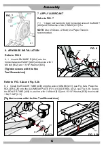
FIG. 3
B13
A12
2. GUIDE RAIL INSTALLATION
Refer to Fig. 2
2.1 Loosely install by hand the 6 M8 screws
[B13] and 6 M8 curve washers [B30].
DO NOT TIGHTEN
until all 6 screws have
been started.
[Tighten screws with the provided M5 Allen
Key]
3. GUIDE RAIL INSTALLATION
Refer to Fig. 3
3.1
Re-Tighten the 2 previously loosened
M8 screws [B13] on the GUIDE RAIL [A12].
[Tighten screws with the provided M5 Allen
Key]
A01
Summary of Contents for ECT400g
Page 1: ...ECT400g Elliptical Cross Trainer ...
Page 27: ...Memo ...


