background image

ECT800g

Elliptical Cross Trainer

Summary of Contents for ECT800g

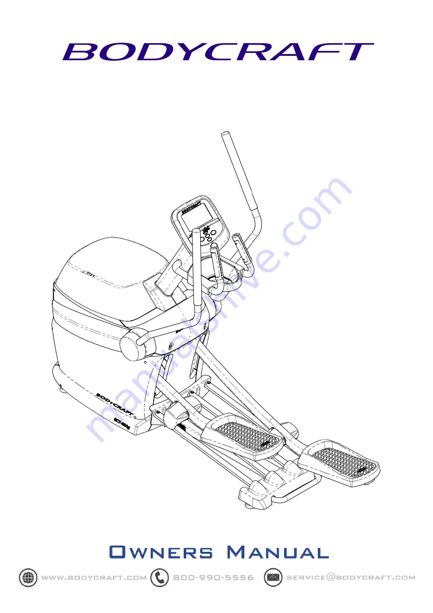
Page 1: ...ECT800g Elliptical Cross Trainer ...

Page 2: ...d the Bodycraft ECT800g will provide an effective workout producing results that will encourage you to reach your fitness goals and maintain the body you have always wanted Spending 15 to 30 minutes a day three times a week is all youneed to start seeing the benefits of a regular exercise program As a premium exercise equipment manufacturer we are committed to your complete satisfaction If you hav...

Page 3: ...nts 2 Placement 3 Assembly 4 Maintenance Adjustment 8 Stretching 9 Computer Operation 10 Troubleshooting 16 Exploded View Assemblies 17 Assemblies Parts List 18 Exploded View 19 Detailed Parts List 20 Warranty 23 TABLE OF CONTENTS ...

Page 4: ...dal first Then step onto the op posite pedal During the workout always hold onto the stationary or upper body han dlebars To ensure the pedals run smoothly push or pull on the upper body handlebars first then follow with leg motion When stepping off the machine while holding onto the stationary handles make sure to step off the highest positioned pedal first and then the lowest 7 Do not use the eq...

Page 5: ...Parts Contents 2 Main Frame Mast Cover Cover Mast Computer Console Right Pedal Left Arm Cover Right Arm Cover Axis Cover Left Arm Right Arm Hardware Pack ...

Page 6: ...o passage around and emergency dismount allow for 20 on at least one side and 20 behind the ECT800g pedals User The ECT800g should not be used by persons weighing more than 350 lbs 160 kgs Wear appropriate exercise clothing without loose articles that could be caught in the ECT800g s moving parts during a workout Personal Safety Stop exercising if you feel faint dizzy or experience pain Do not ins...

Page 7: ...ut 7 as shown Tighten Mast Installation 1 Install the Mast using the four pre installed Bolts as shown Tighten 2 Connect the Wire Harness Connecters located at the bottom of the Mast and at the top of the Main Frame Right Pedal M10 Bolt 5 M10 Nut 7 Mast Wire Harness Connectors Main Frame Preinstalled Bolts x4 ...

Page 8: ...he Computer Console 3 Install the Computer Console to the Mast using the four previously removed screws Be careful not to pinch the wires 4 Battery must be connected before using this console Connect the battery located in the rear of the Computer Console by opening the battery cover and connect the plug as shown Fail to do so will result console to malfunction Main Frame Computer Console Located ...

Page 9: ...10 Nuts 3 as shown 2 Tighten all bolts IMPORTANT Tighten the shorter M8 45 Bolts 6 first on each side and then tighten the M10 90 Bolts 7 and Nuts second to complete the handle bar assembly 3 Install the Left and Right Arm Covers as shown M8 45 Bolt 6 M8 Washers 4 M10 90 Bolt 7 M10 Nut 3 M10 90 Bolt 7 M8 45 Bolt 6 M8 Washers 4 M10 Nut 3 Left Handlebar Right Handlebar Left Arm Cover Right Arm Cover...

Page 10: ...me using two M5 12 Screws 1 as shown Tighten 3 Attach the Mast Cover onto Top Cover around the Mast Note There is a split that allows it to wrap around the mast and set onto the Top Cover ASSEMBLY IS COMPLETE IMPORTANT Please Level the machine prior to use Instructions for leveling are on the next page Cover Mast Cover Axis Cover M5 12 Screw 1 M5 12 Screw 1 M5 12 Screw 2 ...

Page 11: ... The computer uses a rechargeable battery to maintain power if the user were to stop or drop below the minimum rpm s needed for the computer to operate properly If you haven t used your elliptical trainer for a long period of time the battery can drain You can recharge it by simply working out or it can also be charged using an optional power supply Please contact Bodycraft for additional informat...

Page 12: ...utward Pull your feet as close into your groin as possible Gently push your knees towards the floor Hold for 10 counts Toe Touches Slowly bend forward from your waist letting you back and shoulders relax as you stretch toward your toes Reach down as far as you can and hold for 15 counts Hamstring Stretches Sit with your right leg extended Rest the sole of your left foot against your right inner th...

Page 13: ...er column During exercising a column of Dots will blink to indicate the time segment you are currently in and show your workout progress There are also 10 rows of Dots representing 20 levels of resistance Each row represents 2 levels of resistance The appropriate row of Dots will light up when you adjust the resistance level Data display windows Keys Alphanumeric display window Data display window...

Page 14: ...turn to previous activities Basic Operation Power up If this is a self generating product user must pedal the product to power up the console Pause a program If a program is running and there is no RPM for 10 seconds the console will pause and stop accumulating data The pause time is 3 minutes After that the console will reset back to idle mode Within pause mode pedal again to resume the program P...

Page 15: ...ual Random Interval Hill Climb Strength Target HR HR Interval and Custom Quick Start Pressing GO key during idle mode will quick start the console The program will use factory defaults for calculation and display The time will count up and each segment of progress profile equals 1 minute You may stop pedaling at any time or press Home key to end the program Classic programs This group includes Man...

Page 16: ...70 max HR calculated as 220 Age You may also press 5 6 key to adjust the target heart rate setting during heart rate control session of the exercise HR Interval program profile There are two phases of this training Work Interval and Rest Interval After warm up the console will take the default target setting to begin Work interval and adjust the resistance automatically When the target setting is ...

Page 17: ...e that the palms of the hands are touching the contact area of each hand pulse grip Maintain an even pressure on the grips Do not hold the hand pulse grips too tightly Built in Wireless Heart Rate Receiver Note Chest strap transmitter does not come with this unit contact BODYCRAFT or your dealer for purchase This product is equipped with a built in receiver for your heart rate monitoring Any heart...

Page 18: ...his amount of exercise is between 60 and 85 of your maximum heart rate measured during a training session This range allows enough exercise to achieve fitness but not an excessive amount to cause injury Your heart rate is an excellent indicator of the amount of stress placed on the cardiovascular system If exercise intensity is too low or too high no gains will be made in fitness If the intensity ...

Page 19: ...g a reading without holding onto the contact sensors it is likely the wireless receiver that is the problem Wireless Unusually high low or random numbers in the heart rate display indicate a problem Try moistening the electrodes on the heart rate belt The batteries in the belt may be failing Replace batteries or the Heart Rate belt The problem may be caused by interference Televisions microwaves w...

Page 20: ...Assemblies View 17 ...

Page 21: ...15 19 PARTS LIST Assemblies Parts List 18 ...

Page 22: ...Detailed Exploded View 19 ...

Page 23: ... 20 WASHER 26 0 X 35 0 X 1 0 ST BZ 2 21 WASHER WAVE 26 7 X 34 3 X 0 38 2 22 BUSHING BRACK SUPPORT 2 23 WASHER 10 5 X 25 0 X 1 5 ST BZ 2 24 NUT HEX NYLON INSERT STL M10 X 1 25 2 25 SPACER FLANGE TENSIONER 2 26 SCREW M5 X 0 8 X 12 0L SHCS STL GR 8 8 BZ SPRING WASHER 2 27 SPRING WASHER M5 10 28 BOLT M8 X 1 25 X 110L HEX HEAD GR 8 8 BZ 1 29 NUT HEX STYLE 1 M8 X 1 25 BLACK ZINC STL 2 30 TUBE TRANSPORT ...

Page 24: ...DMENT PEDAL 2 57 ASSEMBLY WHEEL RADIAL BALL BEARING SHALLOW PROFILE 4 58 PLASTIC PEDAL 2 59 DUAL LOCK DIA 25 8 60 FOOT PAD PU 2 61 PLASTIC WHEEL COVER 4 62 SLIDE DIA 20 4 63 SCREW M5 X 0 8 X 8 0L PAN HEAD TYPE 1 CROSS RECESSED BZ 4 64 WELDMENT ROCKER 2 65 BEARING FLANGED 25 DIA X 12 L 4 66 PLATE 2P LINK ROCKER 2 67 LEVELER 60MM DIAMETER 5 68 SHEET METAL STAINLESS STEEL RUNNING RAIL 4 69 SCREW M8 X...

Page 25: ...E 1 89 CABLE ASSEMBLY MAST 1 90 SCREW M4 X 24 X 15 TRUSS HEAD TYPE 1 CROSS RECESSED BZ 4 91 ASSEMBLY CONSOLE 1 92 WELDMENT ARM LH 1 93 GRIP HANDLEBAR DIPPED 2 94 WELDMENT ARM RH 1 95 BOLT M10 X 1 5 X 90 0L HEX HEAD GR 8 8 BZ 4 96 PLASTIC HANDLE 2 97 PLASTIC AXIS PANEL 1 98 PLASTIC SHROUD TOP 1 99 LOCK CORE 2 100 SCREW M3 5 X 24 X 10 TRUSS HEAD TYPE 1 CROSS RECESSED BZ 4 101 COVER MAST BOOT 1 102 D...

Page 26: ...ent misuse water tampering unreasonable use unauthorized repairs improper repairs alterations or normal wear and tear This warranty excludes the following 1 The warranty does not cover normal maintenance or labor charges unless labor terms are listed above 2 Normal cosmetic wear on parts such as paint seat coverings walk belts pedal straps wheels foot rails labels and logos 3 Consumables such as b...

Reviews: