background image

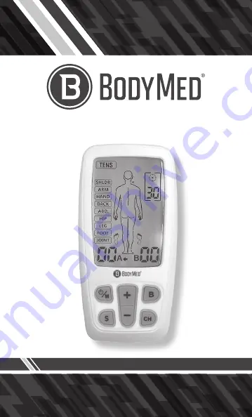
TENS/EMS/Massager Combo

ZZACOMBOBDPT1

Please read this instruction manual 

prior to operating.

Summary of Contents for ZZACOMBOBDPT1

Page 1: ...TENS EMS Massager Combo ZZACOMBOBDPT1 Please read this instruction manual prior to operating ...

Page 2: ...2 All Rights Reserved ZZACOMBOBDPT1 Rev 2019 CAUTION Federal law restricts this device to sale by or on the order of a physician ...

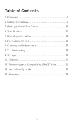
Page 3: ...ing to Know Your Device 13 4 Specification 15 5 Operating Instruction 19 6 Instructions for Use 23 7 Cleaning and Maintenance 29 8 Troubleshooting 32 9 Storage 33 10 Disposal 33 11 Electromagnetic Compatibility EMC Tables 34 12 Normalized Symbols 38 13 Warranty 39 ...

Page 4: ... program controls the generated electric impulses their intensity frequency and pulse width Based on simulating the body s natural pulses the mechanism of electrical stimulation equipment is to create electric impulses that are transcutaneously transmitted to nerves or muscle fibers through the electrode The intensity of the dual channel can be adjusted independently and applied individually to on...

Page 5: ... the injured area along the small nerves leading to the spinal cord There the message is transmitted to different nerves that travel up the spinal cord to the brain Then the pain message is interpreted referred to and pain is felt 1 2 2 What Is TENS TENS Transcutaneous Electrical Nerve Stimulation is effective in relief of pain It is used daily and clinically proven by physiotherapists caregivers ...

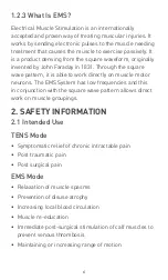
Page 6: ...ttern it is able to work directly on muscle motor neurons The EMS System has low frequencies and this in conjunction with the square wave pattern allows direct work on muscle groupings 2 SAFETY INFORMATION 2 1 Intended Use TENS Mode Symptomatic relief of chronic intractable pain Post traumatic pain Post surgical pain EMS Mode Relaxation of muscle spasms Prevention of disuse atrophy Increasing loca...

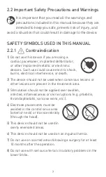
Page 7: ... shock burns electrical interference or death 2 The device should not be used when cancerous lesions or other lesions are present in the treatment area 3 Stimulation should not be applied over swollen infected inflamed areas or skin eruptions e g phlebitis thrombophlebitis varicose veins etc 4 Electrode placements must be avoided in the carotid sinus area anterior neck or transcerebrally through t...

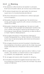
Page 8: ...he airway or cause difficulty in breathing or adverse effects on heart rhythm or blood pressure 6 Do not apply stimulation in the presence of electronic monitoring equipment e g cardiac monitors ECG alarms which may not operate properly when electrical stimulation device is in use 7 Do not apply stimulation across the patient s chest because the introduction of electrical current into the chest ma...

Page 9: ...ve all not on the two large pectoral muscles Here it can increase the risk of ventricular fibrillation and lead to cardiac arrest 15 Never use on the eye area 16 Never use near the genitals 17 Apply the electrodes to clean dry and unbroken skin only 18 Keep electrodes separate during treatment electrodes in contact with other could result in improper stimulation or skin burns 19 Consult your docto...

Page 10: ...lectrical stimulation or silicone rubber If rash develops or pain persists discontinue use and consult a doctor The irritation can usually be reduced by using an alternate conductive medium or alternate electrode placement 8 Electrode placement and stimulation settings should be based on the guidance of prescribing practitioner 9 Effectiveness is highly dependent upon patient selection by a person...

Page 11: ...evices 18 Do not use sharp objects such as pencil point or ballpoint pen to operate the buttons on the control panel 19 Inspect applicator cables and associated connectors before each use 20 Electrical stimulators should be used only with the leads and electrodes recommended by the manufacturer 21 Use this device only with the leads electrodes and accessories recommended by the manufacturer 22 TEN...

Page 12: ... the skin that lack normal sensation 2 2 4 Adverse Reactions 1 Possible skin irritation or electrode burn under the electrodes may occur 2 Possible allergic skin reaction to tape or gel may occur 3 If the stimulation levels are uncomfortable or become uncomfortable reduce the stimulation intensity to a comfortable level and contact your physician if problems persist 4 Patients may experience skin ...

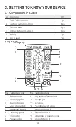
Page 13: ...ption No Function Description 1 Treatment mode 9 Program NO orTreatment time 2 Key locking symbol 10 Massage type 3 Treatment body part 11 SET symbol 4 Model of human body 12 Pulse rate and width symbol 5 Intensity for ChannelA 13 Intensity for Channel B 6 Low battery symbol 14 Symbol of ChannelA 7 Timer symbol 15 Indicator Flag of Channel selection 8 Program symbol 16 Symbol of Channel B 3 2 LCD ...

Page 14: ...tton to enter in the setting mode 4 button At standby or treating mode press the button to increase the intensity of CH1 CH2 or CH1 and CH2 5 B button At standby mode press the B button to select the treatment body part At treating mode press and hold B button to turn on off lock function 6 CH button At standby mode or treating mode press the CH button to select the treatment channel 7 button At t...

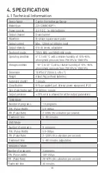
Page 15: ...109 54 5 23mm L x W x T Weight About 76g without batteries Automatic shutoff 1 minute Classification BF type applied part internal power equipment IP22 Size of electrodes pad 50x50mm square Output precision 20 error is allowed for all the output parameters 4 SPECIFICATION 4 1 Technical Information MASSAGE Mode Number of programs 3 programs P W Pulse width 120 250μs P R Pulse Rate 28 97Hz Hz vibrat...

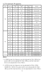
Page 16: ...90 Synchronous Shoulder 45 200 Default 30 Adj 5 90 Synchronous Arm 50 150 Default 30 Adj 5 90 Synchronous Hand 4 200 Default 30 Adj 5 90 Continuous Back 60 200 Default 30 Adj 5 90 Synchronous Abdomen 20 200 Default 30 Adj 5 90 Synchronous Hip 30 150 Default 30 Adj 5 90 Synchronous Leg 80 200 Default 30 Adj 5 90 Synchronous Foot 20 200 Default 30 Adj 5 90 Synchronous Massage Knead 28 44 120 250 30 ...

Page 17: ...17 4 3 The waveform of the stimulation program Continuous Modulation P W Modulation P R TENS Cycle time Cycle time ...

Page 18: ...18 Han EMS Synchronous Continuous Modulation P R W Cycle tim ...

Page 19: ...nt batteries to the Recycle Bin 1 If a battery was swallowed accidentally please seek medical assistance immediately 2 In case of battery leakage please avoid contact with the battery through skin eyes and mucus membranes Once it occurs please wash the contacted area with plenty of clean water and contact your doctor immediately 3 Battery cannot be dismantled thrown into fire or short circuited 4 ...

Page 20: ...p of the main device Ensure the electrode wires are inserted correctly The device has two output receptacles controlled by Channel A and Channel B at the top of the unit You may choose to use one channel with one pair of electrode wires or both channels with two pairs of electrode wires Using both channels gives the user the advantage of stimulating two different areas at the same time Caution Cau...

Page 21: ...of treatment according to the instruction of this user manual Please make the skin clean before use and ensure the skin and electrodes connect well 1 Always remove the electrodes from the skin with a moderate pull in order to avoid injury in the event of highly sensitive skin 2 Before applying the self adhesive electrodes it is recommended to wash and degrease the skin and then dry it 3 Do not tur...

Page 22: ... of the individual patient Every patient is differing from the responds to electrical stimulation and their needs may vary from the conventional settings suggested here If the initial results are not positive tell your physician to choose alternative stimulation settings and or electrode placements Once an acceptable placement has been achieved mark down the electrodes sites and the settings so th...

Page 23: ...6 2 Select Treatment Mode 6 3 Select Treatment Body Part Press the ON OFF M button to turn the device on the LCD will be lit Then it goes into the standby mode as the picture shown Press the ON OFF M button to select which treatment mode TENS MASS EMS you will use The LCD display as follows Based on your need press the B button to select the current treatment body part The LCD displays as follows ...

Page 24: ...plays as follows 6 5 Adjust the Treatment Time 1 In the setting mode press S button to adjust pulse rate pulse width treatment time by setting the parameter Press button to adjust corresponding data Press S button to enter the settings mode The LCD displays as follows The LCD displays as follows ...

Page 25: ...ment channel The LCD displays as follows 6 7 Adjust the Output Intensity Press the button to increase output intensity It will be increased to a higher level after each press The device has totally 40 levels of output intensity Please adjust the intensity to the condition that you feel comfortable The level of output intensity will be shown ...

Page 26: ...sity to a lower level each time When the output intensity of both channels decrease to zero the stimulator will return to the standby mode The LCD displays as follows At treating status press and hold B button to turn on lock function The indicator will display on the LCD This is a safety feature to prevent accidental changes to your settings and to prevent accidentally increasing the output inten...

Page 27: ...rn to level 0 and the symbol A or B twinkles The stimulator returns to the standby mode 6 8 Stop the Treatment and Turn Off the Device Press the ON OFF M button to stop treatment during the treating mode Press the ON OFF M button again to turn off the stimulator and the LCD will be blank 6 10 Low Battery Detection When the battery is low the icon will twinkle to indicate it Stop the device and cha...

Page 28: ...eakage avoid contact with skin eyes and mucus membranes Rinse the affected spots with plenty of clear water immediately and contact a physician right away c Batteries must not be charged dismantled thrown into fire or short circuited d Protect batteries from excess heat Take the batteries out of the device if they are spent or in case you will no longer use them This prevents damage caused by leak...

Page 29: ...es 7 1 4 Clean the surface of the electrode pads carefully with a damp cloth Make sure the device is turned off 7 1 5 For reasons of hygiene each user should use his her own set of electrodes 7 1 6 Do not use any chemical cleaners or abrasive agents for cleaning 7 1 7 Ensure that no water penetrates into the machine Should this happen use the device again only when it is completely dry 7 1 8 Do no...

Page 30: ...mulation settings prescribed by your physician or therapist 7 3 2 It is recommended to use electrodes measuring 50 x 50mm that are manufactured by BodyMed 7 3 3 Inspect your electrodes before every use Replace electrodes if needed Reusable electrodes may cause slight skin irritation lose adhesion and deliver less stimulation when overusing Normally the electrodes can be reused about 20 times 7 3 4...

Page 31: ...de of the protective backing that is labeled with the word 3 It may be helpful to improve repeated application by spreading a few drops of cold water over the adhesive and turn the surface up to air dry Excessive water will reduce the adhesive properties 4 Between use put the electrodes in the re sealable bag and store them in a cool and dry place Caution 1 Do not pull the electrode wire Doing so ...

Page 32: ...up 4 The skin is too dry 1 Check and re paste it on skin 2 Check the connection 3 Replace the battery 4 Wipe the electrode and the skin with a wet cotton cloth Automatic halt in the treatment 1 The electrode loses connection with the skin 2 If the battery is used up 1 Check and place the electrode properly on the skin 2 Replace the battery Rash or tickle on the skin occurs in the treatment 1 The t...

Page 33: ... easily reached by children 3 When not in use for a long period remove the battery before storage 10 DISPOSAL Spent batteries do not belong in the household waste Dispose of the battery according to the current regulations As a consumer you have the obligation to dispose of batteries correctly Consult your municipal authority or your dealer for information about disposal At the end of the product ...

Page 34: ...sions CISPR11 Group 1 The device uses RF energy only for its internal function Therefore its RF emissions are very low and are not likely to cause any interference in nearby electronic equipment RF emissions CISPR11 Class B The device is suitable for use in all establishments including those directly connected to the public low voltage power supply network that supplies to buildings power used for...

Page 35: ...urst IEC 61000 4 4 2 kV for power supply lines Not applicable Not applicable For INTERNALLY POWERED ME EQUIPMENT Surge IEC 61000 4 5 1 kV line s to line s Not applicable Not applicable For INTERNALLY POWERED ME EQUIPMENT Voltage dips short interruptions and voltage variations on power supply input lines IEC 61000 4 11 5 UT 95 dip in UT for 0 5 cycle 40 UT 60 dip in UT for 5 cycles 70 UT 30 dip in ...

Page 36: ...site survey a should be less than the compliance level in each frequency range b Interference may occur in the vicinity of equipment marked with the following symbol NOTE 1 At 80 MHz and 800 MHz the higher frequency range applies NOTE 2 These guidelines may not apply in all situations Electromagnetic propagation is affected by absorption and reflection from structures objects and people a Field st...

Page 37: ... DECT LTE Band 1 3 4 25 UMTS Pulse modulation b 217Hz 2 0 3 28 1845 1970 2450 2400 2570 Bluetooth WLAN 802 11 b g n RFID 2450 LTE Band 7 Pulse modulation b 217Hz 2 0 3 28 5240 5100 5800 WLAN 802 11 a n Pulse modulation b 217Hz 0 2 0 3 9 5500 5785 NOTE If it is necessary to achieve the IMMUNITYTEST LEVEL the distance between the transmitting antenna and the ME EQUIPMENT or ME SYSTEM may be reduced ...

Page 38: ...ible for waste disposal in your area if any questions Applied part of type BF Refer to instruction manual The first number 2 Protect against solid foreign objects of 12 5 mm Ф and greater The second number Protect against vertically falling water drops when enclosure titled up to 15º Vertically falling drops shall have no harmful effects when the enclosure is titled at any angle up to 15º on eithe...

Page 39: ...the warranty period either for the device or for the replacement parts 3 The following cases are excluded under the warranty All damages that arise due to improper operation e g nonobservance of the user instruction All damages due to repairs or tampering by the customer or unauthorized third parities Damages that have arisen during transport from the manufacturer to the consumer or the service ce...

Page 40: ...40 Tens Ems Massager Combo ZZACOMBOBDPT1 ...

Reviews: