background image


- 4 - 

3.


GROUNDING INSTRUCTIONS


The products must be grounded first. If malfunction or breakdown occurs, grounding will provide a 

path of least resistance for electric current to reduce the risk of electric shock.       

The product is equipped with a cord having an equipment-grounding conductor and a grounding 

plug. 

The plug must be plugged into an appropriate outlet that is properly installed and grounded in 

accordance with all local codes and ordinances. 

Danger

 – Improper connection of the equipment-grounding conductor can result in a risk of 

electric shock. Check with a qualified electrician or serviceman if you doubt whether the products 

are properly grounded. Do not modify the plug provided with the product – if it will not fit the 

outlet, have a proper outlet install by a qualified electrician. 


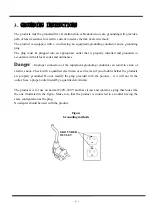
The products is for use on normal 220V~240V and has circuit and contains a plug that looks like 

the one illustrated in the figure. Make sure that the product is connected to an outlet having the 

same configuration as the plug.   

No adapter should be used with the product. 


Figure 

Grounding methods 


GROUNDED 
OUTLET 

Summary of Contents for JFIRE

Page 1: ...Treadmill 1 Retain this owner s manual for future reference Read and follow all instructions in this owner s manual Version A Owner s Manual Model No JFIRE T H E F I T N E S S E Q U I P M E N T...

Page 2: ...1 INDEX 1 OVERVIEW DRAWING 2 IMPORTANT SAFETY INSTRUCTIONS 3 3 GROUNDING INSTRUCTIONS 4 4 PRE ASSEMBLY CHECK LIST 5 ASSEMBLY STEPS 6 CAUTION 7 MAINTENANCE 8 COMPUTER OPERATION INSTRUCTIONS...

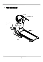
Page 3: ...2 1 OVERVIEW DRAWING Computer Safety Key Clip Power Switch Circuit Breaker Power Cord Frame Base...

Page 4: ...ual Do not use any attachment not recommended by the manufacturer in order to avoid any danger or accidents 4 Never operate the product if it has a damaged cord or plug if it is not working properly i...

Page 5: ...ger Improper connection of the equipment grounding conductor can result in a risk of electric shock Check with a qualified electrician or serviceman if you doubt whether the products are properly grou...

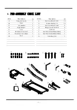
Page 6: ...le 1 a Hex Screw M8xP1 25x15 12 B Frame 1 b Washer 8x 16x1 5t 12 C Left Handrail 1 c Hex Screw M8xP1 25x60 4 D Right Handrail 1 d Philips Screw M5xP0 8x18 4 E Cover 2 e SILICON 1 F Decoration Cover Le...

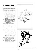
Page 7: ...her b as the right drawing shows Ps 1 To avoid danger always assemble the treadmill with more than two workers do not assemble by yourself Ps 2 When assembling the upright make sure one person holds t...

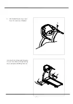
Page 8: ...ter finished the above steps insert Cover E to the above of Handrail E After that fix the left and right Decoration Cover F G to Frame as the right drawing shows and tighten with Philips Screw d d d d...

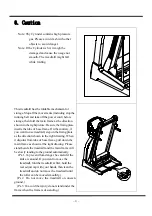
Page 9: ...e On the contrary if you want to use treadmill step on the fixing plate as the direction shown in the right drawing When it disjoins from tube of base frame pull down the main frame as shown at the ri...

Page 10: ...the belt is not in the center be sure to follow above steps Ps 2 The position of running belt might not stay precisely in the center with slightly towards the left and right sides and the situation va...

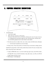
Page 11: ...y clip is not placed in the recess of the console the TIME window will display which means the treadmill can not work normally During exercise if the safety key clip is off then the beeper will sound...

Page 12: ...to control the speed when press the treadmill will stop press once all the values will stop changing the treadmill will pause for 4 minutes and then come back to the START READY position if press once...

Page 13: ...Pre set value 5 km Range of distance 1 9 9 km Step is 0 1 km 2 P1 P5 Program Control Function each PROGRAM has 12 segments 2 1 When the MANUAL LED begin to flash you can press or until the desired LED...

Page 14: ...ent will last for 1 minute when the time is reached the speed and angle value will change directly During exercise you can press or to directly change the speed 2 5 During the function setting of P1 P...

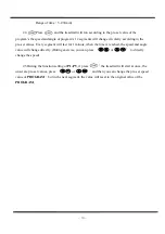
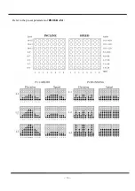
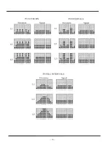
Page 15: ...14 Refer to the pre set parameters of PROGRAM...

Page 16: ...15...

Page 17: ...ale 0 Female After choose the correct option press into the next value setting Weight Pre set value is 70 kg range 30 130 kg Step is 1 kg Press to adjust After choose correct value press and put both...

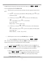
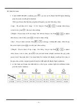
Page 18: ...w 2 3 LCD of AGE light flashes you can press or to adjust age After setting press to another position Age Pre set 30 Range of age 13 80 Step is 1 2 4 At this time LCD of PULSE light flashes the mode w...

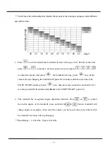
Page 19: ...89 18 192 121 121 36 175 110 110 54 158 100 100 72 141 90 89 19 191 121 121 37 174 110 110 55 157 99 99 73 140 90 88 20 190 120 120 38 173 109 109 56 156 98 98 74 139 90 88 21 189 119 119 39 172 109...

Reviews: