background image

XRG5300

Page 

11

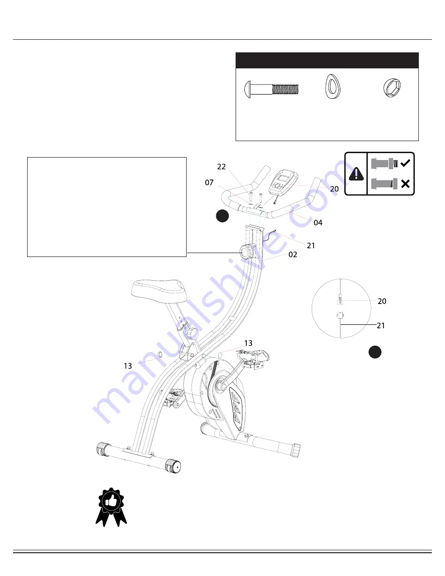
Assembly STEP 5

A.) Attach Handlebar 

(#04)

 to the Main Frame 

(#02)

, and 

secure them together by using two Arc Washers 

(#07)

 and 

two Bolts 

(#22)

.

B.) Attach the Monitor 

(#20)

 by sliding it onto the bracket on 

the Handlebar 

(#04)

.Connect the Wire on the Monitor 

(#20)


to the Monitor Wire 

(#21)

 as shown in the illustration below. 

Lastly, attached two Bolt Caps 

(#13)

 to cover frame's bolt 

and nut as illustrated.

Hardware Required

#22 Bolt (M8x40 mm)

[2 pieces]

#07 Arc Washer (M8) 

 [2 pieces]

THE ASSEMBLY PROCESS IS NOW COMPLETE.

However, for your own safety, please make sure to read this entire Owner’s Manual which 

includes safety instructions and warnings, as well as any safety/warning labels affixed to the 

product before use.  

For your safety , please visually and functionally inspect and test the unit after assembly is 

complete. 

Tension Adjustment

To increase the tension (+ higher level of intensity), turn 

the Tension Controller (#23) in a clockwise direction.

To decrease the tension (- lower level of intensity), turn 

the Tension Controller (#23) in a counter-clockwise 

direction.

"1" is the lowest level of tension (easiest level for  

workout); "8" is the highest level of tension (most difficult 

level for workout). 

A

B

#13 Bolt Cap 

  [2 pieces]

Summary of Contents for XRG5300

Page 1: ...This product is intended for indoor home use only and is not to be used in a commercial setting PRO X BIKE FOLDING INDOOR UPRIGHT CYCLE XRG5300...

Page 2: ...This page is left blank intentionally...

Page 3: ...JURIES AND EVEN DEATH CAN OCCUR IF THE PROPER SAFETY PRECAUTIONS ARE NOT FOLLOWED The diagram below highlights and reviews many of the important Safety and Warning labels also found on the unit Please...

Page 4: ...rs on the proper operation of the equipment and to warn them of the potential hazards If at any time during exercise you feel faint dizzy or experience pain stop and consult your physician Your produc...

Page 5: ...ssembly process This will make it easier to complete certain steps by allowing more tolerance for all the parts to fit properly 2 Do not tighten all the nuts onto the bolts securely until after you ha...

Page 6: ...t Cushion Tube 04 Handlebar 04F Handlebar Foam Grip 05 Front Stabilizer 06 Rear Stabilizer 07 Arc Washer M8 08 Cap Nut M8 09L Left Crank 09R Right Crank 10L Left Pedal 10R Right Pedal 11 Knob Bolt 12...

Page 7: ...the parts and hardware that will be used during the assembly process Not all of the parts and hardware you see here will be used while you are assembling the machine because some of these items are al...

Page 8: ...p 2 pieces Hardware and Tool List Bolt Washer Nut Others Tools Included The following hardware is used to assemble your unit Please take a moment to familiarize yourself with these items PLEASE NOTE M...

Page 9: ...lded and or unattended as shwon in Figure1 After you complete proper assembly you will be able to fold the unit for storage Hardware Required Figure 1 Figure 2 FOLDING INSTRUCTIONS to store the unit T...

Page 10: ...for now Attach the Front Stabilizer 05 to the Shroud Frame 01 then secure them together by using two Arc Washers 07 and two Cap Nuts 08 Attach the Rear Stabilizer 06 to the Main Frame 02 secure them t...

Page 11: ...gnment with the hole on the Shroud Frame 01 as illustrated below Next screw the Knob Bolt 11 through the hole on the Shroud Frame 01 and through the hole on the Seat Cushion Tube 03 Adjust the setting...

Page 12: ...KWISE You will need to use a wrench to tighten if necessary Secure Left Pedal 10L onto the Left Crank 09L by turning the Left Pedal 10L COUNTER CLOCKWISE You will need to use a wrench to tighten if ne...

Page 13: ...ETE However for your own safety please make sure to read this entire Owner s Manual which includes safety instructions and warnings as well as any safety warning labels affixed to the product before u...

Page 14: ...veled CALORIES Displays the amount of calories burned ODOMETER Displays total accumulated distance ODO will reset when MODE is pressed for 3 seconds or when batteries are changed 1 If the display is f...

Page 15: ...rticular installation If this equipment does cause harmful interference to radio or television reception which can be determined by turning the equipment off and on the user is encouraged to try to co...

Page 16: ...mount the unit NOTE To safely move transport and or store the unit please seek the help of capable assistants minimum of 2 people The unit has integrated End Cap 24R L purposely intended to help ease...

Page 17: ...re not damaged 2 You may need to refer to installation assembly directions for the sensor wires in this manual Computer Display If the computer display is blank not displaying any data or does not app...

Page 18: ...toward your body as you tuck your chin and arch your back upward 2 Return to the starting position slowly 1 Sit with your leg extended and bend your right knee as you cross your right leg over your le...

Page 19: ...a support with your left hand 2 Flex your right leg behind you grasp your ankle or foot with your right hand and pull your foot toward your buttocks Keep your back straight and right knee pointed down...

Page 20: ...ion below and keep this manual along with your sales receipt as proof of purchase Serial Number Date of Purchase Retailer Body Flex Sports Inc 21717 Ferrero Parkway Walnut CA 91789 Phone 1 888 266 678...

Reviews: