


8
2014/11/10V1.0+V1.0
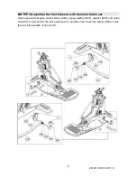
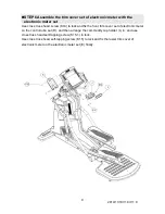
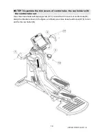
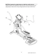
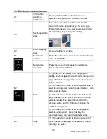
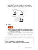
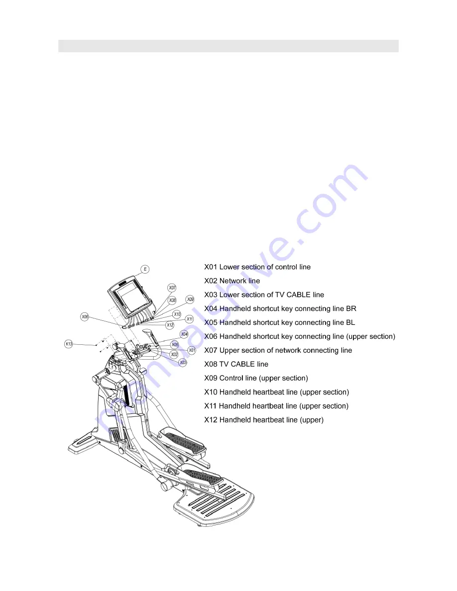
STEP 5 Assemble the electronic meter set with the control tube set
Connect the lines according to the figure. Pay attention to the directivity. Please do not
insert forcibly if the directivity is wrong.
Align the screw holes on the rear part of the electronic meter set (E) with the screw holes of
the control tube set (D), and use cross truss head screw (K13) to lock and fix the electronic
meter.
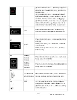
During assembly, please make sure the screws are firmly locked to avoid damage of the
electronic meter due to loosening of the screw.
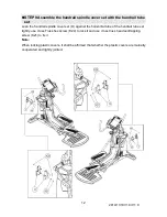
Notes:
The holes shall be aligned and the directivity of the electronic meter shall be
affirmed during assembly.
The wires of the electronic meter shall be arranged in cooperation with the holes
of the electronic meter holder, so as to avoid wire short easily caused by bending
of the electric wires.


