SX-16 Nightsun
®
Searchlight System
Maintenance Manual
Document 031734-1/Revision A
031734-1 Revision B
January 27, 2014
4.5.4
Cable Ties
The motor wires are cut at the factory so that they are long enough to allow a full range of Gimbal
motion. The length of the wire usually exceeds the amount needed to permit a full range of motion.
Consequently, the excess wire is tied down with cable ties (also called lead dressing or lead dress).
Inspect the condition of the cable ties, and adjust them so that the service loop is long enough but not
too long.
If you must replace the cable ties, use black replacement ties that are specifically rated for outdoor
use. The white and clear ties are not resistant to outdoor levels of sunlight, and they will deteriorate
rapidly.
4.6
Mechanical Stops
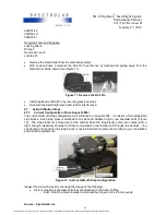
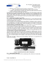
Mechanical stops limit the motion of the Gimbal in both Azimuth and Elevation. These mechanical
stops prevent the Searchlight from being pointed in unwanted directions. When the Gimbal or
Searchlight hits these mechanical stops while the motor is still running, the clutches in the Gearboxes
begin to slip. This stops the motion of the Gimbal or Searchlight.
The Azimuth and Elevation mechanical stops should be inspected as part of a pre-flight inspection
and every 6 months or 300 flight hours or 100 operation hours.
In addition, to the mechanical stops (supplied by Spectrolab), some Searchlight systems include
electronically programmable stops as part of ancillary equipment (such as a moving camera) that has
been specially installed. Adjustment of these programmable stops is addressed in the documentation
that accompanies the ancillary equipment.
4.6.1
Elevation Motion Stops
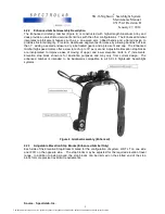
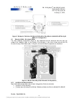
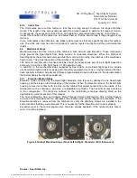
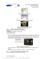
Elevation motion is limited by the Searchlight Elevation stop (Figure 9) attached to the Searchlight
housing, and the stops on the inside edge of the Gimbal. When the Elevation stop on the Searchlight
housing comes into contact with the stop on the Gimbal that project outward from the inside of the
Gimbal arm such as hardware, stop pins, or adjustable stop blocks. The travel limits vary according
to the configuration. The limits are outlined on the coordinating envelope drawing listed on the
Applicable Documents
section of this manual
The
Test of Elevation Stop and Adapter Plate Threaded Holes
and
Elevation Stop Internal Square
Drive and Stop Hardware section
addresses the elevation stop and its inspection procedures. If the
Elevation Gearbox is removed from the Gimbal arm, verify the attaching screws are installed in the
same locations that they were removed. This is necessary for the Elevation stop to work properly.
Excessive wear to the central square drive hole also causes backlash. If the central square hole is
worn, it must be replaced.
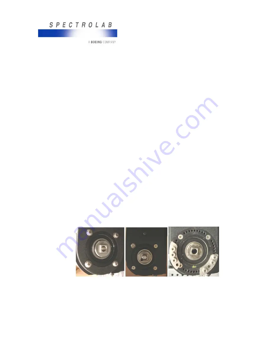
Figure 8 Gimbal Elevation Stops (From Left to Right: Standard, IFCO, Enhanced)
Source: Spectrolab, Inc.
14
The document reference is online, please check the correspondence between the online documentation and the printed version.


