SX-16 Nightsun
®
Searchlight System
Maintenance Manual
Document 031734-1/Revision A
031734-1 Revision B
January 27, 2014
022955-22
019059-111
022955-51
Required Tools and Supplies:
Locking Pliers
Wrench
Hex Hex Wrench
Loctite 272
•
Remove the Searchlight from the Gimbal Assembly.
•
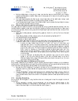
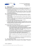
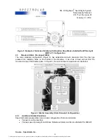
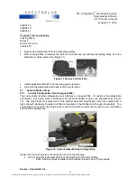
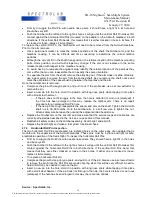
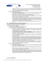
With Locking Pliers, compress the Roll Pin then remove by twisting and pulling away from the
Gimbal Arm at the same time (Figure 11).
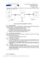
Figure 11 Remove the Roll Pin
•
Install replacement Roll Pin by reversing previous steps.
•
Re-install the Searchlight Head and test for interference.
4.7
Azimuth Motion Stops
4.7.1
Current Configuration (Since August 2004)
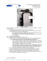
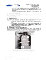
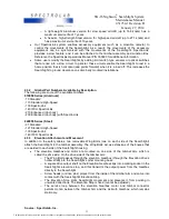
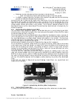
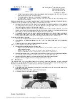
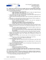
The current Azimuth stop configuration was introduced in August 2004. It consists of two adjustable
stop blocks. Each stop block is attached to the Azimuth Adapter ring by two shoulder bolts (Figure
12). The stop blocks limit movement of the Gimbal when the stop blocks come into contact with a
high- strength stationary shoulder bolt that is mounted on the Gimbal Arm through the doubler. You
can detach and reposition the stop blocks to restrict Azimuth movement according to your installation
and aircraft requirements.
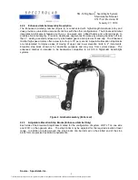
Figure 12 Current Azimuth Stop Configuration
Inspect the Azimuth stops by checking the torque of the following:
•
All four stop block shoulder bolts that are attached to the Azimuth Ring
o
Each 8-32 stop block shoulder bolt should be torque to 20 ±2 inch-pounds.
Source: Spectrolab, Inc.
16
The document reference is online, please check the correspondence between the online documentation and the printed version.

