SX-16 Nightsun
®
Searchlight System
Maintenance Manual
Document 031734-1/Revision A
031734-1 Revision B
January 27, 2014
•
Stationary precision shoulder bolt that is mounted on the Gimbal arm.
o
Each ¼”-20 precision shoulder bolt should be torque to 78 ±2 inch-pounds.
•
In addition, regularly inspect the condition of the stop block shoulder bolts and the stationary
precision shoulder bolt. Replace them if necessary.
Azimuth motion also is limited by the length of the motor wiring. If it is long enough, the motor (and
Searchlight) wiring enables the Searchlight to rotate a maximum of 170° to the left and 170° to the
right of a center position with respect to the Gimbal (this assumes that the Searchlight/Gimbal are
pointed directly forward with relation to the aircraft). The maximum potential movement of the
Searchlight, however, will be compromised if the wire becomes twisted around or hampered by the
Gimbal components.
4.7.2
Old Configuration (Before August 2004)
The old Azimuth stop configuration applies to all Gimbals that were in service before August 2004.
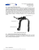
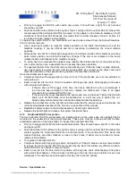
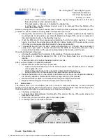
Azimuth motion is limited by the length of the motor wiring and the position of three Roll Pins (called
mechanical stops) as shown in Figure 13.
If it is long enough, the motor (and Searchlight) wiring enables the Searchlight to rotate a maximum of
170° to the left and 170° to the right of a center position with respect to the Gimbal (this assumes that
the Searchlight/Gimbal are pointed directly forward with relation to the aircraft). The maximum
potential movement of the Searchlight, however, will be compromised if the wire becomes twisted
around or hampered by the Gimbal components.
Azimuth motion is limited by the position of three Roll Pins that are 3/16” in diameter.
One of the Roll Pins (called the vertical Roll Pin) is pressed into the top outside edge of the Gimbal
arm’s doubler plate. When fully inserted, it projects 0.375” above the surface of the Gimbal arm and
moves with the Gimbal arm’s rotation. The position of this pin is fixed. It moves back and forth
between the two adjustable horizontal Roll Pins. When it comes into contact with either one of the
horizontal Roll Pins, the motion of the Searchlight stops.
Two of the Roll Pins (called the horizontal Roll Pins) are pressed into radiating holes on the outer
edge of the Gearbox adapter, which is mounted on the underside of the Azimuth Gearbox. These two
Roll Pins can be moved to a number of different positions in the radiating holes of the adapter to halt
the motion of the Searchlight at various points. When the Roll Pin on the Gimbal comes into contact
with one of the Roll Pins pressed into the adapter (in either direction), the motion of the Searchlight
stops.
All Roll Pins are subject to fatigue and eventual breakage. Inspect them on a regular basis and
replace them if necessary.
Figure 13 Azimuth Stop Roll Pins (Older Configuration)
4.7.3
Vertical Roll Pin Inspection
To inspect the vertical Roll Pin (located on the top outside edge of the Gimbal arm’s doubler plate):
Source: Spectrolab, Inc.
17
The document reference is online, please check the correspondence between the online documentation and the printed version.

