SX-16 Nightsun
®
Searchlight System
Maintenance Manual
Document 031734-1/Revision A
031734-1 Revision B
January 27, 2014
•
First try to wiggle the Roll Pin with needle nose pliers. It should have a tight fit in its hole and
should be very stiff.
•
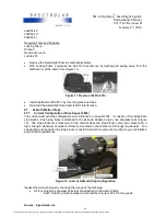
Push the Gimbal to the left and to the right as far as it will go until the vertical Roll Pin makes firm
contact against the horizontal Roll Pins (mounted on the adapter on the Azimuth Gearbox) in both
directions. If the vertical Roll Pin bends, this means that it is either cracked or loose in its hole. If it
is cracked or loose, replace it immediately.
To replace the vertical Roll Pin, the Gimbal arm will need to be removed from the Azimuth Gearbox.
Prior to the arm removal:
•
Use a permanent marker to mark the relative positions of the shaft, the Gimbal arm, and the
Gearbox housing. It can be difficult and time consuming to determine the correct relative
positions.
•
Although the arm will fit on the shaft in any position, the relative location of the Gearbox mounting
bolts, motor position, and Azimuth stops may change if the arm is not replaced in the same
relative location with respect to the Gearbox housing.
•
To avoid having to recreate the original setup, identify the relative location of the parts as they
come off so that you can reassemble them in exactly the same orientation.
•
To separate the arm from the shaft, remove the attaching nut. If the arm does not slide off easily,
use a gear puller to remove the arm from the splined shaft. As you remove the shaft, notice and
mark the orientation of the spacer bushing between the Gearbox and the arm
Once the Gimbal arm is removed:
•
Compress the pin with vise-grip pliers, and pull it out. If the pin breaks, use a screw extractor to
remove the pin.
•
Insert a new pin into the hole. Hold it in position with long nose pliers while tapping it into place
with a small steel hammer.
o
If the pin does not fit snuggly in the hole, the hole is distorted or worn out (enlarged). If
the hole has been enlarged in this way, replace the Gimbal arm. There is no repair
procedure for an enlarged Roll Pin hole.
o
If the new pin fits snug, reassemble the spacer and arm on the shaft. Tighten the Azimuth
shaft nut to 50-60 foot-lbs. Hold the Gimbal arm in a soft jaw vise to tighten the nut.
Attach safety wire between the nut and the adjacent drilled head screw.
•
Replace the Gimbal arm on the aircraft, and make sure that the service loops and cable ties are
correctly adjusted as described in the
Service Loops
section of this manual.
•
Reattach all safety cables on the Gimbal assembly, Searchlight, and aircraft.
•
Replace the Searchlight and make a full system functional check.
4.7.4
Horizontal Roll Pin Inspection
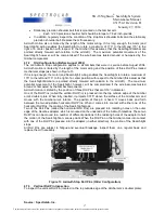
The two horizontal Roll Pins are pressed into radiating holes on the outer edge of an adapter that is
mounted on the underside of the Azimuth Gearbox. These pins must be in place and tight for safe,
predictable operation of the Searchlight. To inspect the horizontal Roll Pins:
•
First try to wiggle the Roll Pins with needle nose pliers. They should have a tight fit in the holes
and be very stiff.
•
Push the Gimbal to the left and to the right as far as it will go until the vertical Roll Pin makes firm
contact against the horizontal Roll Pins in both directions. If the vertical Roll Pins bend, this
means that they are either cracked or loose in their holes. If either one is cracked or loose,
replace it immediately.
•
To replace a horizontal Roll Pin:
•
Compress the pin with vise-grip type pliers, and pull it out. If the pin breaks, use a screw extractor
to remove the pin. Since the Roll Pins are made of spring steel, this will be very difficult. An extra-
hard drill bit may be needed to remove the pin.
•
Insert a new pin into the hole. Hold it in position with long nose pliers while tapping it into place
with a small steel hammer. If the pin does not fit snug in the hole, the hole is distorted or worn out
(enlarged). If the hole has been enlarged in this way, there are two options:
Source: Spectrolab, Inc.
18
The document reference is online, please check the correspondence between the online documentation and the printed version.

