SX-16 Nightsun
®
Searchlight System
Maintenance Manual
Document 031734-1/Revision A
031734-1 Revision B
January 27, 2014
o
Connect one end of the bulkhead to Gimbal cable to the bulkhead through connector.
On the other end, connect the Gimbal portion of the cable to the 4 pin connector on
the Gimbal.
o
Connect the Searchlight portion of the cable to the 12-pin connector on the
Searchlight.
3.5.3
Junction Box to Input Power
Make sure that the Control Box On switch is set to the Off position.
Connect one end of the power cable to the J3 connector on the Junction Box. Connect the other end
of the power cable to the power source.
4.0 GIMBAL ASSEMBLY
4.1
Functional Description
The Gimbal assembly (Figure 3) has a U-shaped yoke (called a Gimbal arm) made of ¼” x 3” high
strength aluminum or steel. When fully assembled, it serves the following functions:
o
Mechanically supports the Searchlight and the attachment to the aircraft.
o
Provides the electrical and communication link between the Searchlight and Junction
Box.
o
Contains gears, electronic equipment, and separate DC motors that adjust the
Searchlight’s Azimuth and Elevation positions. Consequently, the Gimbal assembly
enables the Searchlight to be pointed in various directions.
4.2
Gimbal Configurations Available
4.2.1
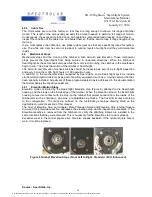
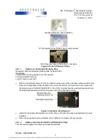
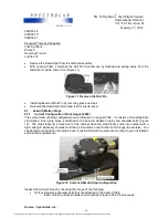
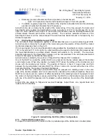
Standard Gimbal Assembly (Current) Description
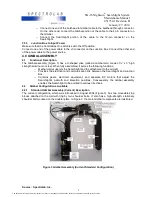
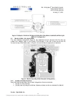
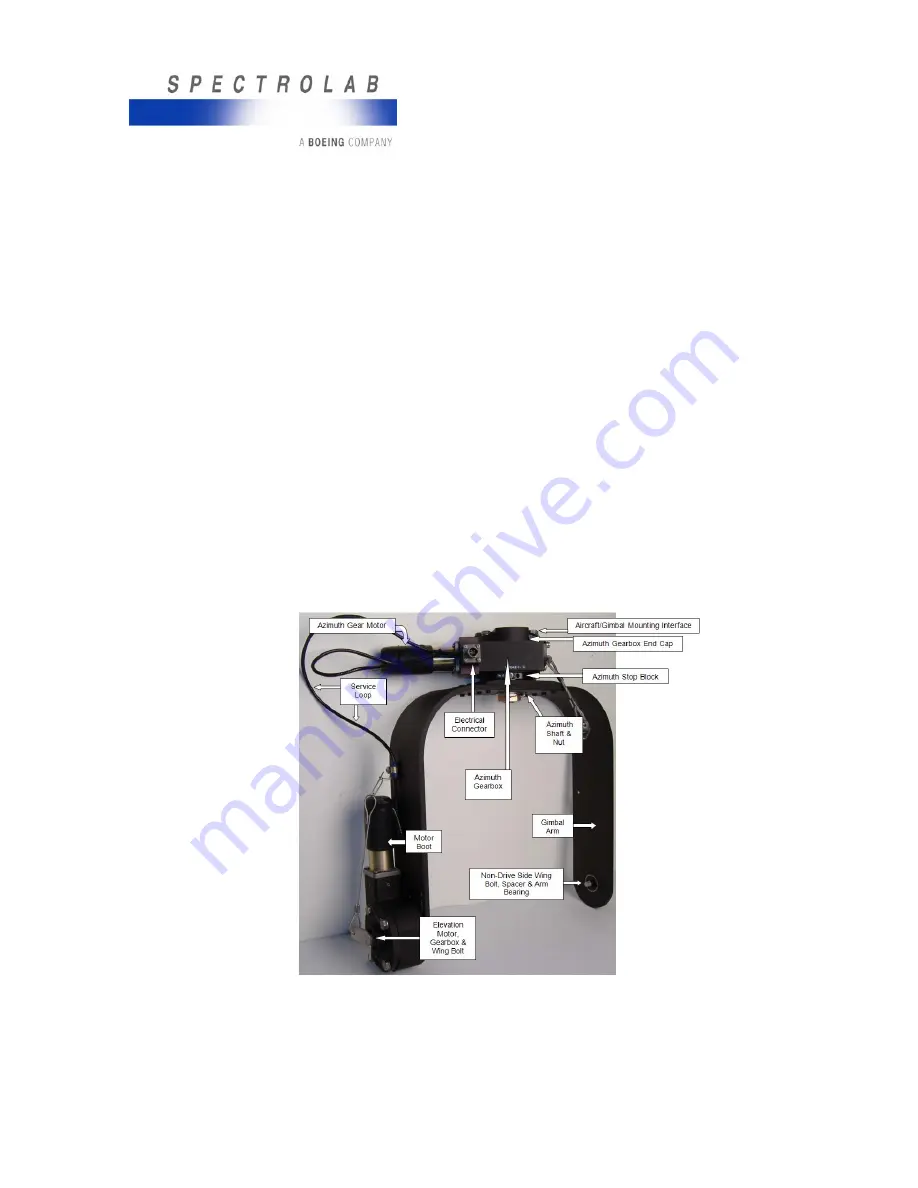
The current configuration, which was introduced in August 2004 (Figure 3), has two moveable stop
blocks attached to the Azimuth ring by two shoulder bolts. It also has a high-strength, stationary
shoulder bolt mounted on the doubler plate. In Figure 3, the main Gimbal components are illustrated.
Figure 3 Gimbal Assembly (Current Standard Configuration)
Source: Spectrolab, Inc.
8
The document reference is online, please check the correspondence between the online documentation and the printed version.


