SX-16 Nightsun
®
Searchlight System
Maintenance Manual
Document 031734-1/Revision A
031734-1 Revision B
January 27, 2014
4.5.2
Inspection Procedure
4.5.2.1
Standard Connector
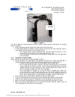
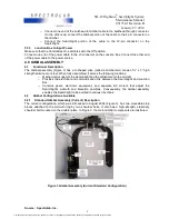
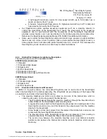
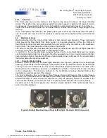
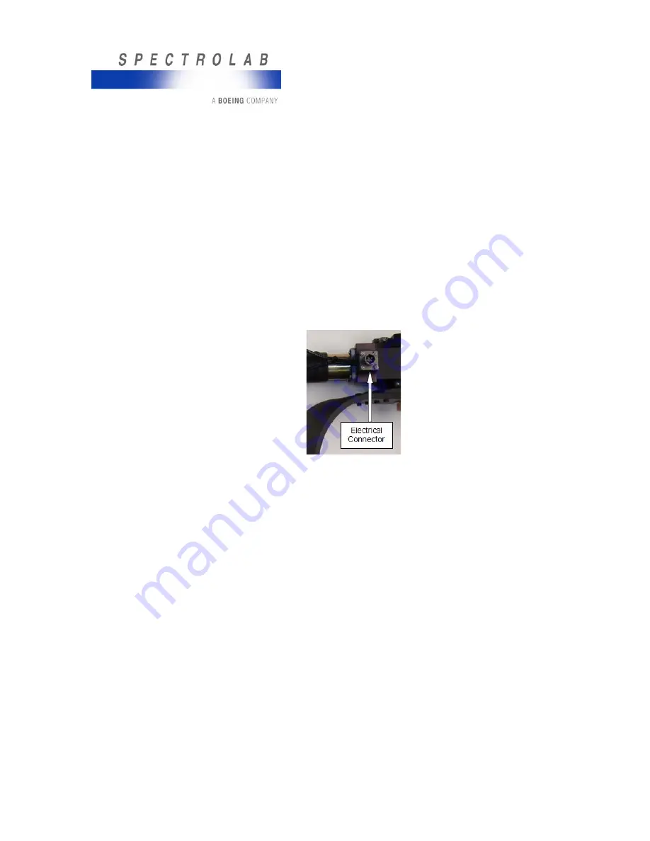
The Spectrolab Gimbal has a circular 4-pin quick-release standard connector that supplies power to
the Gimbal motors (the Searchlight has its own connector). The connector is mounted on an
aluminum bracket that screws into the Azimuth Gearbox housing with four mounting screws (Figure
7).
•
The bracket can be installed so that it points to the right, left, or down.
•
The gold plated pins on the connector connect to a mating connector on the external
Searchlight/Gimbal cable.
•
Inspect the connector to verify its condition:
o
The pins should be shiny and free of corrosion or tarnish, and the body of the
connector should not be severely corroded or broken.
o
The small radial pins on the outside of the connector shell must be intact for the
connector to be seated properly.
o
The four mounting screws that hold the connector to the mounting bracket should be
in place and tight. If they are not tight, remove the screws, apply a drop of Loctite
®
on
the loose screws, replace them, and tighten them.
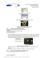
Figure 7 Gimbal Electrical Connector
4.5.2.2
Alternate Connectors
A few Gimbals that are used on fixed wing aircraft and on some boats will have an alternate
connector. Further, if you have added aftermarket sensors or switches to the Gimbal, these sensors
or switches will have a second, separate connector. If not, you may have to replace the standard 4-
pin connector with one that has more pins.
4.5.2.3
Motor Wires
The condition of all motor wires is important. These wires must be able to flex, permitting the motion
that takes place with respect to the Azimuth Gearbox and Gimbal arm. Inspect the motor wires for
chafing, pinched wires, the condition of the insulation, evidence of stress, and general serviceability. If
the wires are not in good condition, refer to the
Replacement of Wiring and Electrical Connector
for
replacement procedures.
4.5.3
Service Loops
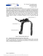
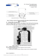
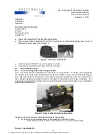
The Gimbal arm rotates with respect to the fixed Azimuth Gearbox. Consequently, the wire that runs
between the elevation motor and the electrical connector on the Azimuth Gearbox requires a service
loop to permit the motion of the Gimbal arm (Figure 3).
The service loop should be long enough to enable the Gimbal to move to its mechanical limits in both
directions without pulling on the motor wire. If the motor wire pulls repeatedly, it will eventually break
off from the terminals on the elevation motor (inside the boot).
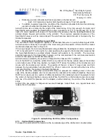
Inspect the service loop as you manually push the Gimbal from one limit to the other. The wire must
not pull on the motor connection or on the area where it enters the connector bracket. If the wire pulls,
readjust the cable ties (also called lead dressing or lead dress) to increase the amount of free wire
until the wire no longer pulls.
Source: Spectrolab, Inc.
13
The document reference is online, please check the correspondence between the online documentation and the printed version.


