background image

Installation


Specification 
 

Dimensions: Height 590mm Depth 458mm Width 396mm 
Weight: 35Kg 
Voltage: 115-230V 
Frequency: 50/60Hz 
Full load current: 12.5A 
Power: 1100W 
Capacity:350m

3

/h 


Connection to Power Supply 

Please follow the above specification when selecting the 
power supply outlet for the V600 system, ensure the power 
supply is suitable before connecting the V600 system. 
 
Check the Integrity of the electrical power cable, if the 
supply cord is damaged the extraction unit should not be 
connected to the mains. The supply cord should only be 

replaced by a BOFA engineer as an electrical safety 
test may be required after replacement. 
 

The V600  

MUST

 be connected to a properly earthed outlet. 


If your V600 system was ordered with any 
optional extras please read section 

4.03


before 

the power connection is made as additional connections 
may be required before power is connected to the 
extractor. 

 
Connect the power cable to an isolated electrical supply. 
 
The mains socket should be installed near the extractor it 
should be easily accessible and able to be switched On/ Off. 
The cable run should be arranged so as not to create a trip 
hazard.  


Cabinets 

Cabinets normally have a 75mm 0r 100mm spigot for fume 
extraction. For best performance use the same diameter 
hose as the spigot and reduce at the extractor end if 
necessary. 

Keep the hose run as short as possible. 


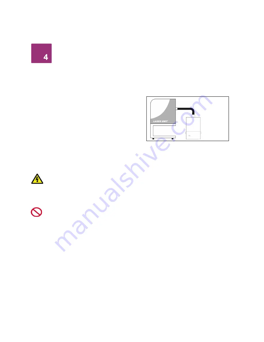
Connection to extraction unit 
All ductwork should be installed and connected to the 
extraction unit before the extraction system is turned on.


Exhausting filtered air outside 

If requested your extraction unit will have been fitted with 
an exhaust outlet spigot. This provides a connection point 
for exhaust pipework to be fitted. It is important to keep any 
ducting to a minimum, in order to reduce back pressure 
within the system. 


02 

Summary of Contents for V600

Page 1: ...V600 Issue 2 Jan 2017 ...

Page 2: ......

Page 3: ...Overview 01 Control Panel Feet Clips Handles ...

Page 4: ...Overview 02 Air Inlet Mains Inlet Signal Cable Inlet Air Outlet Mains Isolation Switch Motor Cooling Override Switch ...

Page 5: ...Overview Flow Adjustment 03 Company Branding Filter Blocked Filter 75 full System Running Clean VOC Alarm ...

Page 6: ...c shock or injury 1 Always isolate the system from the mains power supply before removing the pump motor access panel 2 Use only as described in this manual 3 Connect the system to a properly grounded outlet Dangers to eyes breathing and skin Once used the filters within the V600 system may contain a mixture of particulates some of which may be sub micron size When the used filters are moved it ma...

Page 7: ...e Relevant approval markings logos PLEASE NOTE If the equipment is used in a manner not specified by the manufacturer the protection provided by the equipment maybe compromised Fire Risk Warning In the very rare event that a burning ember or spark is drawn into the fume extraction unit it may be possible that the filters will ignite Whilst any resultant fire would typically be retained within the ...

Page 8: ...500 mm space is available around any vented panels on the extractor to ensure adequate airflow 2 Check the filter is located in its correct position before replacing the lid and securing the clips Caution Due to the weight of the extractor suitable lifting equipment should be used and with regard to appropriate safety precautions See Appendix for product weight details Caution Do not block or cove...

Page 9: ...rm Nozzle Extraction The stay put arm should be mounted as close as possible to the marking point using the horseshoe clips Unscrew the push fit connector from the other side of the flexible hose Cut the flexible hose to suit the distance back to the extractor connection and push onto the extractor inlet Purge air should be kept to a minimum where possible to prevent the fume being blown away from...

Page 10: ...tion is made as additional connections may be required before power is connected to the extractor Connect the power cable to an isolated electrical supply The mains socket should be installed near the extractor it should be easily accessible and able to be switched On Off The cable run should be arranged so as not to create a trip hazard Cabinets Cabinets normally have a 75mm 0r 100mm spigot for f...

Page 11: ...either DC voltage input or the Volt free input The override feature can be toggled On Off by a switch mounted on the internal motor access panel see below for switch location Switch in On position In this position the extractor will require a start signal either Voltage input or Volt free depending on the requested specification to enable the motor within the extraction unit Switch in Off position...

Page 12: ...ally blocked filters The extractor and all pipe work must be fully installed and connected before the airflow is set To set the airflow Press the Up arrow button to increase airflow and press the down arrow button to decrease airflow The level of airflow is indicated by the vertical row of six blue LEDs to the right of the mains isolation switch As the airflow increases more blue LEDs light up and...

Page 13: ...lter changes should be maintained by the user The filters require attention when the display shows the configuration shown on the next page or when the extractor no longer removes fume efficiently It is recommended that a spare set of filters are kept on site to avoid prolonged unit unavailability Part numbers for replacement filters can be found on the filters fitted in your system To prevent ove...

Page 14: ...olate the electrical supply to the extractor 2 Undo the two clips on the sides of the unit and remove the motor section using the two handles on the sides of the lid 3 Lift the filter out of the unit Once removed it is recommend that the used filters are bagged and sealed 4 Lower the new filter into position If the current pre filter is found to be serviceable place into the new combined filter 5 ...

Page 15: ...Combined Filter Date Engineer Filter disposal The V600 combined filter is manufactured from non toxic materials Filters are not re usable cleaning used filters is not recommended The method of disposal of the used filters depends on the material deposited on them For your guidance Deposit EWC Listing Comment Non Hazardous 15 02 03 Can be disposed of as non hazardous waste Hazardous 15 02 02M The t...

Page 16: ...l operating speed Size Metric mm Imperial inches Height 590 23 1 Depth 458 18 Width 396 15 6 Filters Filter Type Surface area Efficiency Pre Filter F8 4 2m2 95 0 9 microns HEPA Filter Combined filter 2 1 m2 99 997 0 3µ Filter Type Carbon Type Amount Carbon filter combined filter Activated Carbon 8 5kgs Environmental operating range Temperature 5o C to 40o C Humidity Max 80 RH up to 31o C Max 50 RH...

Page 17: ...Information BOFA Headquarters 21 22 Balena Close Creekmoor industrial Estate Poole Dorset BH17 7DX UK Phone 44 0 1202 699444 BOFA Americas 303 S Madison Street Staunton Illnois 62088 USA Phone 001 618 205 5007 ...

Reviews: