background image

Installation 


Optional added features 

The V600 can be configured to suit customer specification. These 
optional extras would be discussed, arranged and installed prior to 
delivery.  
(

If unsure what features your system is equipped with please 

contact the seller with the unit serial number, 

(Refer to section 

2


for location) 

who will be able to advise what specification has 

been supplied.


Remote Stop/Start feature 

Enables the extraction unit to be remotely turned On / Off via an 
external signal. 

Note: Care must be taken to ensure that the system is correctly 
wired in order for the extraction unit to function correctly. 

DC Voltage input 

This configuration requires the Black & Red cores of the signal 
cable (Refer to section 

1


for location) to be connected to a known 

and tested DC power supply, in order to start the extractor. 
 
The operating voltage for this signal is 24VDC. Only this voltage 
should be connected. Voltages connected outside of this range 
may cause irreversible damage to the relay. 

Red cable = V+ 
Black cable = V- 

When the extractor is provided with the correct DC voltage the 
motor will start and maintain the set flow rate (Refer to section 

5


for how to set the flow) when the DC voltage is removed the motor 
will slow down and come to a stop. 
 

The extractor will need to be turned on (See section 

5


for turning 

the extractor on) in order for this feature to operate. 

Override 

Enables the extractor to operate fully with or without either DC 
voltage input or the Volt free input. 
The override feature can be toggled On / Off by a switch mounted 
on the internal motor access panel (see below for switch location)  
 

Switch in “On” position 

In this position the extractor will require a start signal (either 
Voltage input or Volt free, depending on the requested 
specification) to enable the motor within the extraction unit. 

Switch in “Off” position 

In this position the extractor motor will run without the 
requirement for an external start signal. This feature is useful for 
engineers carrying out works/ tests on the extractor without the 
need for the laser / auxiliary signal being present.   

Filter Blocked / System Fail Signal 

With this option the extraction system will output a signal to alert 
the user when the extractor has failed or when the filters are 
blocked. 


This feature will not directly stop the extractor from running 
correctly, but if fitted this feature should be terminated correctly 
before power is applied to the extraction system. 
 

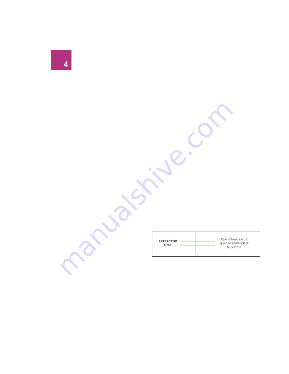
Connection specification 

This signal is available via the Green and White cores of the signal 
cable. The system will provide a volt free Open / Closed signal that 
can be connected to an external interface, beacon or warning 
device following the specification below.


Maximum input voltage: 24V AC 


Maximum current load: 3A @ AC 
OR


Maximum input voltage: 24V DC


Maximum input load: 3A @ DC


Filter Signal 

When the filters become blocked or the system develops a fault 
the connection between the Green & White cables will become 
“Open” 
When the extraction system is running normally the connection 
between the Green & White cables will become “Closed”


03 

Summary of Contents for V600

Page 1: ...V600 Issue 2 Jan 2017 ...

Page 2: ......

Page 3: ...Overview 01 Control Panel Feet Clips Handles ...

Page 4: ...Overview 02 Air Inlet Mains Inlet Signal Cable Inlet Air Outlet Mains Isolation Switch Motor Cooling Override Switch ...

Page 5: ...Overview Flow Adjustment 03 Company Branding Filter Blocked Filter 75 full System Running Clean VOC Alarm ...

Page 6: ...c shock or injury 1 Always isolate the system from the mains power supply before removing the pump motor access panel 2 Use only as described in this manual 3 Connect the system to a properly grounded outlet Dangers to eyes breathing and skin Once used the filters within the V600 system may contain a mixture of particulates some of which may be sub micron size When the used filters are moved it ma...

Page 7: ...e Relevant approval markings logos PLEASE NOTE If the equipment is used in a manner not specified by the manufacturer the protection provided by the equipment maybe compromised Fire Risk Warning In the very rare event that a burning ember or spark is drawn into the fume extraction unit it may be possible that the filters will ignite Whilst any resultant fire would typically be retained within the ...

Page 8: ...500 mm space is available around any vented panels on the extractor to ensure adequate airflow 2 Check the filter is located in its correct position before replacing the lid and securing the clips Caution Due to the weight of the extractor suitable lifting equipment should be used and with regard to appropriate safety precautions See Appendix for product weight details Caution Do not block or cove...

Page 9: ...rm Nozzle Extraction The stay put arm should be mounted as close as possible to the marking point using the horseshoe clips Unscrew the push fit connector from the other side of the flexible hose Cut the flexible hose to suit the distance back to the extractor connection and push onto the extractor inlet Purge air should be kept to a minimum where possible to prevent the fume being blown away from...

Page 10: ...tion is made as additional connections may be required before power is connected to the extractor Connect the power cable to an isolated electrical supply The mains socket should be installed near the extractor it should be easily accessible and able to be switched On Off The cable run should be arranged so as not to create a trip hazard Cabinets Cabinets normally have a 75mm 0r 100mm spigot for f...

Page 11: ...either DC voltage input or the Volt free input The override feature can be toggled On Off by a switch mounted on the internal motor access panel see below for switch location Switch in On position In this position the extractor will require a start signal either Voltage input or Volt free depending on the requested specification to enable the motor within the extraction unit Switch in Off position...

Page 12: ...ally blocked filters The extractor and all pipe work must be fully installed and connected before the airflow is set To set the airflow Press the Up arrow button to increase airflow and press the down arrow button to decrease airflow The level of airflow is indicated by the vertical row of six blue LEDs to the right of the mains isolation switch As the airflow increases more blue LEDs light up and...

Page 13: ...lter changes should be maintained by the user The filters require attention when the display shows the configuration shown on the next page or when the extractor no longer removes fume efficiently It is recommended that a spare set of filters are kept on site to avoid prolonged unit unavailability Part numbers for replacement filters can be found on the filters fitted in your system To prevent ove...

Page 14: ...olate the electrical supply to the extractor 2 Undo the two clips on the sides of the unit and remove the motor section using the two handles on the sides of the lid 3 Lift the filter out of the unit Once removed it is recommend that the used filters are bagged and sealed 4 Lower the new filter into position If the current pre filter is found to be serviceable place into the new combined filter 5 ...

Page 15: ...Combined Filter Date Engineer Filter disposal The V600 combined filter is manufactured from non toxic materials Filters are not re usable cleaning used filters is not recommended The method of disposal of the used filters depends on the material deposited on them For your guidance Deposit EWC Listing Comment Non Hazardous 15 02 03 Can be disposed of as non hazardous waste Hazardous 15 02 02M The t...

Page 16: ...l operating speed Size Metric mm Imperial inches Height 590 23 1 Depth 458 18 Width 396 15 6 Filters Filter Type Surface area Efficiency Pre Filter F8 4 2m2 95 0 9 microns HEPA Filter Combined filter 2 1 m2 99 997 0 3µ Filter Type Carbon Type Amount Carbon filter combined filter Activated Carbon 8 5kgs Environmental operating range Temperature 5o C to 40o C Humidity Max 80 RH up to 31o C Max 50 RH...

Page 17: ...Information BOFA Headquarters 21 22 Balena Close Creekmoor industrial Estate Poole Dorset BH17 7DX UK Phone 44 0 1202 699444 BOFA Americas 303 S Madison Street Staunton Illnois 62088 USA Phone 001 618 205 5007 ...

Reviews: