7
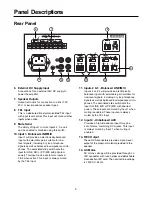
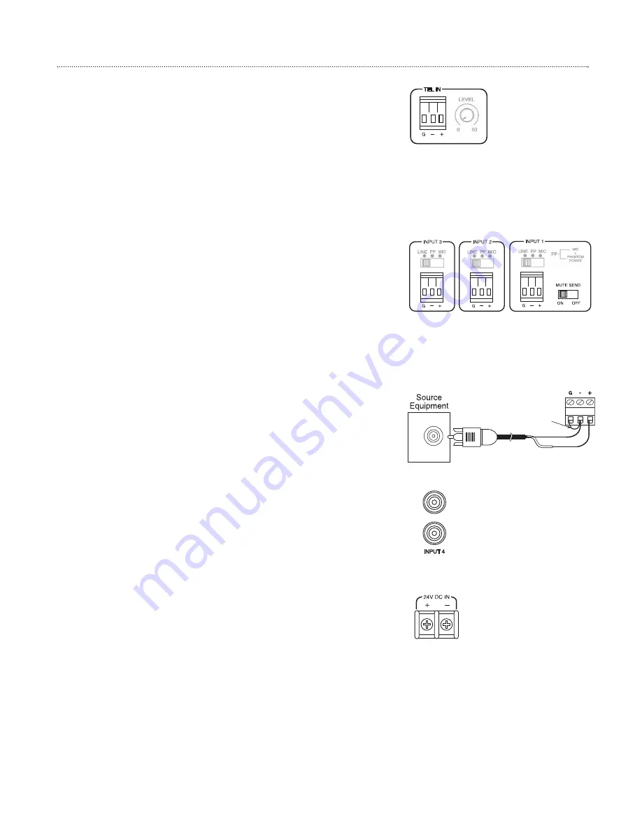
Balanced - TEL Input
The TEL input is a transformer-balanced input. The telephone signal
should be Dry Audio with no DC voltage between the signal lines. If the
telephone has a DC voltage across it, a telephone interface adapter
should be used to provide a compatible signal for this input. Wire one of
the signal lines “+” terminal and the other to the “-” terminal. Generally
there is no shield for the telephone signal, but if the cable has one,
connect it to the G terminal. The “+” & “-” designations for this input refer
to the phase of the signal, so even if the “+” & “-” connections were
reversed the amp would still work fine. TEL Input will mute all other inputs
when active.
Balanced - LINE/MIC Inputs (1 to 3)
Inputs 1 through 3 are compatible with balanced telephone/line-level
signals and microphone-level signals. Wiring for balanced MIC and
balanced line signals are the same with the positive signal line going to
“+”, the negative going to “-” and the cable’s shield going to G. The + and -
designations refer only to the phase of the signal, so even if the + and -
connections were reversed, the amp would still work fine. See the
Operation section for details on setting the associated switches. Input 1
has the ability to mute Inputs 2, 3, and 4 when active depending on the
setting of the Mute Send switch. These inputs are always muted by TEL
Input when active.
Unbalanced - LINE Inputs (1 to 3)
Inputs 1 through 3 can be wired to accept mono unbalanced signal
sources. Convert a balanced input to unbalanced by wiring a shorting
jumper from the G terminal to the “-”. The unbalanced signalʼs hot lead is
then wired to the “+” terminal and the shield is connected to the G terminal.
AUX Input 4
Input 4 is a stereo-combining input, compatible with unbalanced line-level
(AUX) signals. This input may be muted by audio activity at Input 1
depending on the setting of the Mute Send switch. This input is always
muted by TEL Input when active.
24V DC IN
The amplifier can be powered by an external power source that can sup-
ply 24V DC and 3 amps of current. Wire the power source to the terminals
observing the polarities marked on the terminals.
Input Connections
JUMPER
HOT
SHIELD

