background image

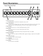
Panel Descriptions

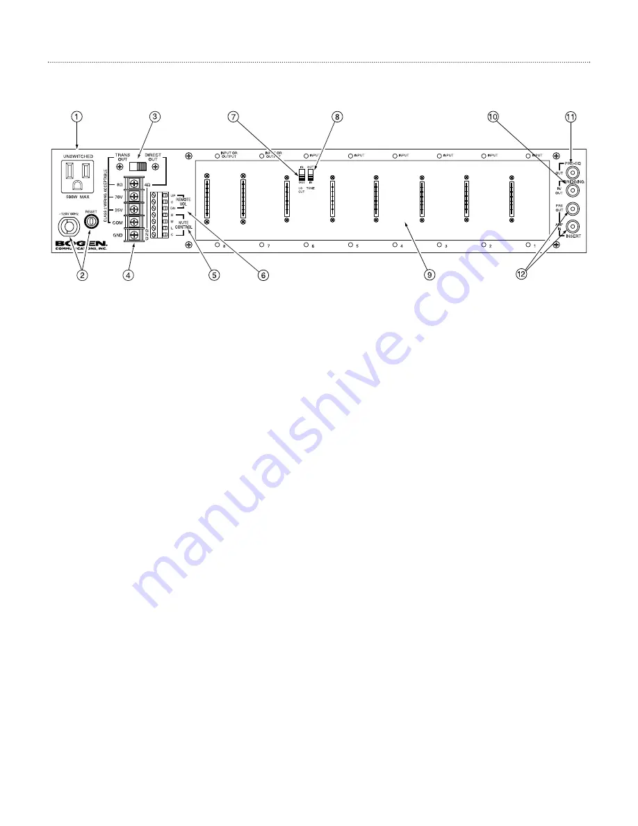
Power Vector Rear Panel

1

.AC Receptacle

A grounded, unswitched AC convenience receptacle with a 500W maximum capacity is provided for external
equipment.

2

.AC Line Cord and Circuit Breaker

A grounded, 3-wire AC line cord provides power to the amplifier and is protected by a resettable circuit 
breaker.

3.Trans Output / Direct Out Selector

Allows selection of either transformer-coupled outputs (70V, 25V, and 8-ohm) or a direct low-impedance 
(4-ohm minimum) output.A locking device is included to avoid accidental switching.

4. Speaker Output Barrier Strip

A 5-position barrier strip, with clamping washers, provides connections for speaker loads.

5. Mute Control Terminals

Provides access to mute buses for external control and system expansion.

6. Remote Volume  Control Terminals

Three terminals are provided for connection of a remote station to control the amplifier’s motorized Master
Volume Control.

7. Low-Cut Switch

A slide switch (located in module bay 6) that allows roll off of frequencies below 

1

25 Hz.

8.Tone Control Bypass Switch

A slide switch (located in module bay 6) that allows the effects of the bass and treble controls to be bypassed.

9. Module Bays

The amplifier has eight module bays, all of which can accommodate input modules, with two bays (bays 7 
and 8) that can accommodate either input or output modules.

1

0. Bridging Jack

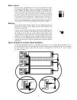
An RCA connector that allows the bridging of Power Vectors together for system expansion.

11

. Pre-EQ Output

An unbalanced RCA buffer output whose signal includes all volume controls, tone controls, and output module
signal processing, but before (pre-EQ) any external signal-processing equipment connected to the Signal-
Processing Insert jacks.

1

2. Insert Jacks

A pair of RCA connectors allow external equipment to be inserted between the pre-amp output and the power
amp input. Inserting a plug into the jack labeled “IN” automatically breaks the internal connection between the
amplifier’s pre-amp section and power amp section.The insert connections are unbalanced.

3

Summary of Contents for Power Vector V100

Page 1: ...Power Vector Amplifiers V35 V60 V100 V150 V250 Models Installation and Use Manual 2004 Bogen Communications Inc All rights reserved Specifications subject to change without notice 54 2072 01B 0401 ...

Page 2: ...cian for replacement of the obsolete outlet 10 Protect the power cord from being walked on or pinched particularly at plugs convenience receptacles and the point where they exit from the apparatus 11 Only use attachments accessories specified by the manufacturer 12 Unplug this apparatus during lightning storms or when unused for long periods of time 13 Refer all servicing to qualified service pers...

Page 3: ...w Impedance Speaker Connections 6 COM and GND Terminals 7 Remote Volume Control 7 Pre EQ Output 7 Signal Processing Inserts 7 Mute Control 8 Bridging 8 System Expansion of Power Vector Amplifiers 8 OPERATION 9 10 Front Panel Controls Indicators 9 Input Volume Controls 9 Signal Clip Indicator 9 Base and Treble Controls 9 Master Volume Control 9 Average Peak Switch LED Output Meter 9 Power Switch Po...

Page 4: ...Control Controls the amount of cut or boost of treble frequencies above 10 kHz 4 Bass Control Controls the amount of cut or boost of bass frequencies below 100 Hz 5 LED Output Meter An 11 segment LED output level meter monitors the output level of the power amplifier 6 Average Peak Switch This switch determines whether the LED Output Meter registers the average or peak level of the amplifier s out...

Page 5: ...Control 7 Low Cut Switch A slide switch located in module bay 6 that allows roll off of frequencies below 125 Hz 8 Tone Control Bypass Switch A slide switch located in module bay 6 that allows the effects of the bass and treble controls to be bypassed 9 Module Bays The amplifier has eight module bays all of which can accommodate input modules with two bays bays 7 and 8 that can accommodate either ...

Page 6: ...s Shelf Table Mounting When using a shelf or table mount the amplifier should stand alone with no equipment on top of it or below it especially for theV100 V60 andV35 models If the amplifier must be stacked with other equipment care must be taken to ensure that all the minimum clearance distances are met and that the equipment below the amplifier produces little significant heat Rubber feet are in...

Page 7: ... so that the input function of the module bay is not lost when an output module is installed Input Modules Functionality The PowerVector series of amplifiers accepts Bogen s new advanced input modules which provide a wide range of input types allowing the amplifier inputs to be custom configured in both type and number for a particular application Input modules can be installed into any of the 8 m...

Page 8: ...and the GND terminal Make sure the selector switch is in the DIRECT OUT position Bypassing the output transformer and driving the speaker load directly provides the advantage of better bass response To maximize the power delivered to the speakers their combined load impedance should be 4 ohms Connecting higher load impedances is electrically acceptable but the mismatch in load impedance will cause...

Page 9: ...e direction and decrease the level of the MasterVolume control The impedance of the shorting connections must be less than 100 ohms in order to operate the control The Bogen Remote Volume Control Panel Model RVCP provides a simple and elegant means of remote control Alternatively a SPDT spring loaded center off switch or two SPST push button switches can provide the necessary contacts for remote c...

Page 10: ...d allows the connecting of Power Vector units for system expansion and simple room combining This function is bi directional Any signal received will be amplified and any signal sent can be used by another PowerVector amp The signal levels at the bridging jack will drop by one half with two Power Vectors tied together and by two thirds with three units tied together Because of the attenuation of t...

Page 11: ...0 Hz This filter shape helps to avoid overdriving the output transformer with low frequency signals that may cause noticeable distortion due to magnetic saturation of the transformer s core Master Volume Control The overall volume level of the amplifier is set by a Master Volume control The Master Volume control is motorized and can be controlled by manually adjusting the knob or by a remotely mou...

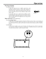
Page 12: ...e loosened screw and align it with the switch Tighten the screw making sure the lock has not shifted Other Controls Located In Module Bay 6 Tone Control Bypass Switch A slide switch that can bypass the effects of the Bass and Treble controls is located on the back plane of module bay 6 It is sometimes desirable to bypass the tone controls when other forms of system equalization are used A screwdri...

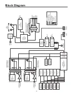
Page 13: ...Block Diagram 11 ...
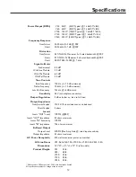
Page 14: ...inimum Low Cut Frequency 125 Hz 6 dB octave Sensitivity 0 4V at backplane connector Output Regulation 2 dB or better no load to full load Output Impedance Transformer Coupled 70V 25V 8 ohms balanced or unbalanced Direct Coupled 4 ohms Inserts Insert OUT Level 1VRMS FRP Insert OUT Impedance 50 ohms maximum Insert IN Sensitivity 1VRMS Insert IN Impedance 10k ohms minimum Buffered Output Output Level...

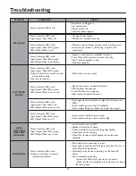
Page 15: ...ons Trans Out load on wrong tap Bass control boosted too much POOR LOW FREQ RESPONSE NO BASS Power Indicator LED is red Input Signal Clip LED is green LED Output Meter not in red Lo cut switch is set to ON Speakers wired out of phase Check module bass control setting if available Check bass control setting Note Transformer coupled speakers have less bass response Power Indicator LED is red Volume ...

Page 16: ...ased upon warranty contract tort or other wise shall be limited to the price of the product In no event shall Bogen be liable for special incidental or consequential dam ages including but not limited to loss of profits loss of data or loss of use damages arising out of the manufacture sale or sup plying of products even if Bogen has been advised of the possibility of such damages or losses Some S...

Reviews: